


1. Introduction
Additive manufacturing, also known as 3D printing, is a highly convenient and beneficial technology for many industries and individuals in manufacturing and design. As the name suggests, it involves the process of building by adding materials, such as layer-by-layer stacking to create a three-dimensional model or using adhesive and powdered materials to create objects from scratch. Conceptually, additive manufacturing is the direct and rapid production of a 3D model from a computer-aided design (CAD) file without the need for part-specific tools or dies [1]. Users can directly manufacture their 3D CAD models. For factories and engineers, they can print a prototype to inspect potential issues before mass production visually. Artists can create high-precision models and sculptures. For inventors and creators, 3D printing enables them to obtain appropriately sized parts whenever needed. Fused Deposition Modeling (FDM) 3D printers are the most common type of printer due to their low cost and ease of use. They work by heating and melting thermoplastic filament and extruding it through a nozzle with a fine opening. The melted material is deposited onto a build plate or previously solidified layers, and once the temperature drops below the solidification temperature, it solidifies. This layer-by-layer accumulation of material forms the final product. However, most affordable FDM printers need more advanced features to address common issues, making completing a 3D printing project challenging. The complete process of FDM 3D printing includes handling the CAD model and selecting processing parameters. This article will analyze potential problems, errors, and their impacts at these stages of the printing process.
2. Possible errors during CAD model processing
Usually, a 3D model is created using 3D design software such as SolidWorks, AutoCAD, and others. For later printing, the 3D model needs to be saved in the STL format. Then, this STL file is further processed into a G-code file, which can be read by a 3D printer using slicing software. By going through these steps, a 3D model can be properly prepared for 3D printing.
2.1. Conversion from CAD model to STL file
Once there is a CAD 3D model, it needs to be saved in an STL format for further printing. During this step, the surface of the CAD model will be triangulated, meaning it will be filled with a large number of triangular facets that approximate the original surface of the CAD model. Therefore, the original smooth surfaces of one or more solid pieces will be replaced by numerous small triangles. The resulting STL file will resemble the original CAD model. These triangles will have normal vectors, and vertex coordinates [2]. In Figure 1, we can see that the original CAD model is a sphere. By saving it as an STL file, it becomes a framework composed of multiple triangles that approximate the shape of the sphere.
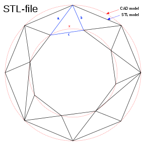 Figure 1. A CAD representation of a torus (shown as two concentric red circles) and an STL approximation of the same shape (composed of triangular planes) [3].
Since the STL file approximates the original CAD model, there will be some degree of error determined by the chord height. The chord height represents the radial distance between the approximating triangle and the surface contour, as shown in Figure 2. The maximum distance from the surface to the edges of the triangle is the chord height. Different chord heights can lead to significantly different results and variations in error. Smaller chord heights result in a higher degree of approximation for the STL model, but they also increase the number of triangular facets and the size of the STL file. As a result, data processing speed decreases, and processing time increases accordingly [4]. Furthermore, since the STL file is an approximate representation of the triangulated surface of the CAD model, the errors introduced during the conversion cannot be eliminated but only reduced. Therefore, during the CAD-to-STL file conversion process, there will be some unavoidable errors in FDM and most other 3D printers.
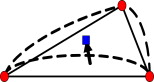 Figure 2. Chord height error [5].
2.2. Slicing error
After obtaining the STL file, it needs to undergo the corresponding slicing process. With a specified thickness constraint, the slicing starts along the Z-axis printing direction. It calculates the two-dimensional contour information by intersecting the model with a series of cutting planes perpendicular to the Z-axis, thus completing the slicing process. Then, the obtained series of two-dimensional contour data undergoes path planning for filling, converting the data into G-code instructions. This instruction file is sent to the 3D printer, which gradually accumulates and prints according to the G-code instructions, resulting in a solid model.
To rapidly conduct the data processing, the slicing process plays a crucial role as it directly affects the accuracy and complexity of the manufacturing process. Slicing is to convert a complex 3D model into a series of simple two-dimensional contour data, indirectly describing the original model. Following the principles of rapid prototyping, after selecting an appropriate slicing direction, a series of parallel cutting planes intersect with the model to calculate the cross-sectional contours of each layer [6].
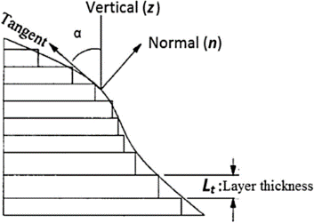
Figure 3. Stepper error in FDM printing [7].
Figure 3 illustrates that there is excess material and a step effect in the printed model, referred to as the staircase effect in rapid prototyping. There is a certain level of error between the printed model and the theoretical model. The surface accuracy of the printed model decreases as the layer thickness increases and improves as the layer thickness decreases [8]. Additionally, if the surface of the STL model is more gradient, the error in the resulting interface contour will be more significant.
3. Printing parameters
The processing parameters mainly include printing speed, printing temperature, bed temperature, and layer height. These parameters need to be set before printing.
3.1. Print speed
Print speed refers to the movement speed of the print head during printing. It determines the efficiency of the printing process, with higher print speeds leading to increased efficiency. However, the nozzle's extrusion speed limits the print speed. Suppose the print speed is set significantly higher than the extrusion speed without adjusting the extrusion speed accordingly. In that case, it will result in shorter heating time per unit length of filament, insufficient melting of the filament, and reduced flowability. This can cause filament breakage during printing, leading to print failures.
On the other hand, if the set print speed is lower than the extrusion speed, it will result in insufficient space for filament deposition during the printing process. This can lead to uneven filament distribution on the printed surface, with excessive filament adhering around the nozzle, potentially causing nozzle clogging and print failures. Additionally, swift movement of the print head can reduce the adhesion strength of the filament. The extruded filament can be easily displaced by the movement of the print head, resulting in warping and deformation of the printed object.
3.2. Extruder temperature
Print temperature refers to the heating temperature of the print head during printing. The print temperature affects the filament's adhesion, deposition, and flowability. Different filaments require different print temperatures. Therefore, the print temperature needs to be controlled within a reasonable range based on the specific filament to ensure sufficient melting and flow of the filament at the nozzle during operation. The primary filament materials used in FDM printers are PLA (Polylactic Acid) and ABS (Acrylonitrile et al.). Different filaments have different melting points and temperature requirements, so parameter settings should be specific to the filament being used.
In an FDM 3D printer, the print head feeds the printing material into the nozzle, which is clamped and secured by the filament drive gear. The feed gear pushes the material into the heating chamber and is heated to a molten state. Meanwhile, the rear portion of the printing material continues to be pushed forward, driving the molten front section of the filament to be extruded through the nozzle. It then cools and solidifies on the print bed, forming the cross-sectional contour of the object. During the process, the heat from the nozzle can transfer through the guiding tube, causing the printing material to soften prematurely, resulting in filament clogs or breakage, which can affect print accuracy. When extruded from the nozzle, the molten printing material carries residual heat, maintaining a semi-molten state. If cooling is not timely, the stacking of subsequent layers can cause collapse and damage to the previous layer, ultimately resulting in decreased dimensional accuracy of the printed object [9].
3.3. Bed temperature
Bed temperature refers to the temperature of the platform on which the 3D-printed object adheres. It usually takes some time to preheat the bed to the desired temperature and then maintain that temperature throughout the printing process. The required bed temperature varies depending on the material being used.
One possible issue caused by bed temperature is curling. Heating the print bed plays a crucial role in reducing warping. When the filament is extruded from the nozzle and deposited on the heated bed, if the bed is not heated throughout the process, there will be significant temperature gradients during the cooling and solidification of the material. The longer cooling time increases internal stress in the material, leading to curling deformation. Preheating and maintaining the bed temperature throughout the print can reduce the temperature difference, lower internal stress levels, and minimize shrinkage deformation, thus helping to eliminate curling deformation. However, suppose the bed temperature is too high. In that case, the deposited filament will remain in a molten state for a prolonged period, resulting in excessive bonding and loss of the object's original shape, leading to decreased dimensional accuracy and print failures. [10]
Therefore, to reduce the possibility of curling, choosing the appropriate bed temperature is essential based on the material being used. The recommended temperature range for PLA is typically 50-70 degrees Celsius [11], while ABS requires a temperature range of 100-110 degrees Celsius [12].
3.4. Layer height
Layer height refers to the thickness of each layer in a 3D-printed model after it has been sliced. When setting the layer height, a more minor thickness results in more layers and better mechanical properties of the printed object. However, if the layer height is too small, there may need to be more clearance between the nozzle and the print bed, leading to poor filament extrusion or clogging. Conversely, a more considerable layer height reduces the number of layers and improves printing efficiency. However, if the layer height is too large, the relative cooling time for each layer increases, resulting in adequate bonding strength between layers. This can lead to delamination or collapse of the object, resulting in reduced mechanical properties and overall print quality. Therefore, setting an appropriate layer height is crucial to achieving optimal mechanical performance and print quality.
Typically, the layer height parameter can be set between 0.1 mm and 0.2 mm, and it should not exceed the diameter of the extruder [13].
4. Conclusion
This article discusses the workflow of FDM 3D printing, including converting a CAD model to STL format and further converting it to Gcode for the 3D printer. It explores the potential errors that may arise during these conversions. It highlights the importance of processing parameters such as print speed, extruder temperature, bed temperature, and layer height in achieving print quality and accuracy. However, the article does not quantitatively investigate the mentioned errors, nor does it delve into potential issues related to the mechanical framework of FDM 3D printers, such as the use of stepper motors to drive extruder movement.
There is room for further research and improvement in this area. It would be beneficial to conduct in-depth studies to quantify the errors discussed and address the mechanical issues that may arise in FDM 3D printers. For example, exploring the advantages and disadvantages of using stepper motors to drive extruder movement could provide valuable insights. The aim would be to enhance and refine the understanding of the FDM printing process and help researchers and users effectively address potential issues that may arise.