


1. Introduction
In the game of basketball, interference violation is a rule that is extremely difficult to call. According to the rules of the National Basketball Association (NBA), it will be a foul if the basketball is interfered with by a defender during its descent or while inside the cylinder of the hoop. Interference calls are made by the Tracking Referee (T).
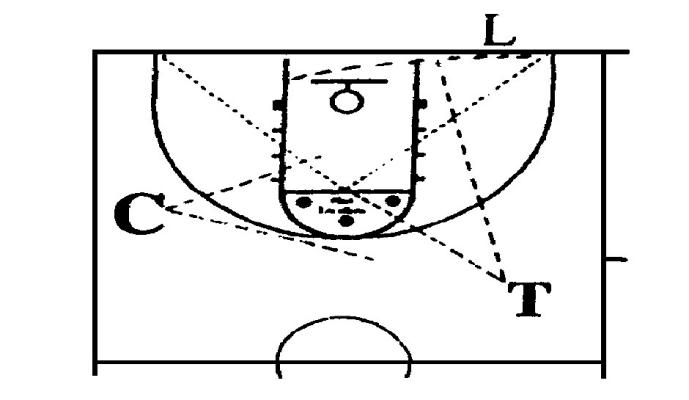
Figure 1. Diagram of the three-person referee [1].
Figure 1 shows the regular standings of the tracking judges. The distance between the referee and the basket is usually greater than 9 meters, which makes it extremely difficult to judge with the human eye, and misjudgments happen from time to time. In the season 2018 of NBA, missed interference calls in the final moments of the game directly affect the game. Such a call is bound to weaken the fairness of the game and cause a loss of economic benefits to the business league.
By establishing a multi-camera real-time video monitoring system with artificial intelligence automatic identification judgment, this project overcomes many blind spots of human eye judgment, efficiently and accurately completes the penalty, improves the accuracy of the referee's ruling on basketball interference ball violation, and enhances the fairness and spectacle of the game.
2. Literature review
Commercial leagues have developed expensive video officiating as an in-game adjudication aid. In the NBA, for example, the league spent $15 million in 2014 to build the Replay Center, consisting of 101 screens and 21 employees[2]. In the CBA, on the other hand, the video replay system needs to be improved[3] since cannot cover all regular season games due to lack of funds, and other middle and lower leagues cannot even guarantee a regular three-person referee combination, leaving a big gap in penalty.
There are only two patents for automatic penalty awarding devices dedicated to ball interference, and none of them is widely used, mainly because the systems are too complicated for practical operation. Maanshan Normal University of Higher Education has developed a new type of basketball board[4] that uses a radar sensor for ball interference calls. The device requires each court to be equipped with a new basketball board, which is impractical for low and mid-level leagues. Wuhan University of Technology developed an interference ball awarding system[5] based on multiple light emitters and multiple infrared sensors, which have a complex design and are also hard to operate. Therefore, an easy-to-operate, low-cost interference ball penalty system has a promising future.
In China National Knowledge Internet, there are 10,385 papers related to "visual recognition", which is already a well-studied field, while there are 65 papers related to "electronic adjudication", and only one paper of crossover between the two, which indicates that the application of video intelligent recognition technology has not been explored.
After fully comparing the advantages and disadvantages of monocular vision and binocular vision, monocular vision is used as the recognition method. In comparison, the monocular vision has the following advantages.
For low and mid-level basketball leagues, resources are very limited, so cost is an important consideration. Monocular vision recognition only needs one camera to cover a specific area, and the capital cost is half of the binocular vision recognition. At the same time, binocular vision recognition requires strict control of the relative positions of the cameras, making the time cost of using the system much higher than that of monocular vision recognition. Monocular vision will have higher accuracy and robustness due to the geometric model constraint advantage. According to Zhou Kun[6], in the interval above 11 meters, which is the active interval of this system, monocular vision has a clear advantage over binocular vision in terms of recognition accuracy.
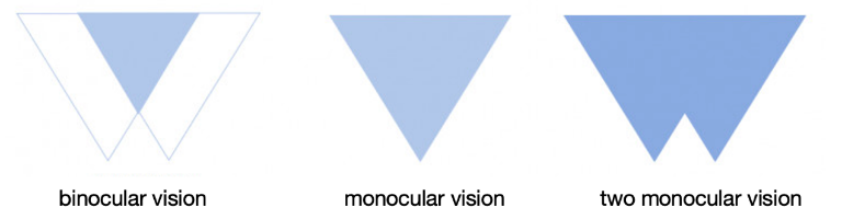
Figure 2. Visual recognition field of view comparison.
As shown in Figure 2, the field of view of monocular vision is much larger than the binocular field of view. In this subject, the size of the field of view to be covered is 420 square meters, and it is difficult for binocular vision to achieve full coverage. Therefore, monocular vision recognition is more suitable for this system.
Compared with binocular vision, monocular vision also has disadvantages such as the complexity of the system and the need for rigid body assistance. These disadvantages can be solved by algorithms, which I will present later.
3. Methodology
In practice, at least two cameras will be placed at fixed points directly under the basketball hoop, with their respective optical axes parallel to the floor facing the opposing team's basket, responsible for covering the call of the other team.
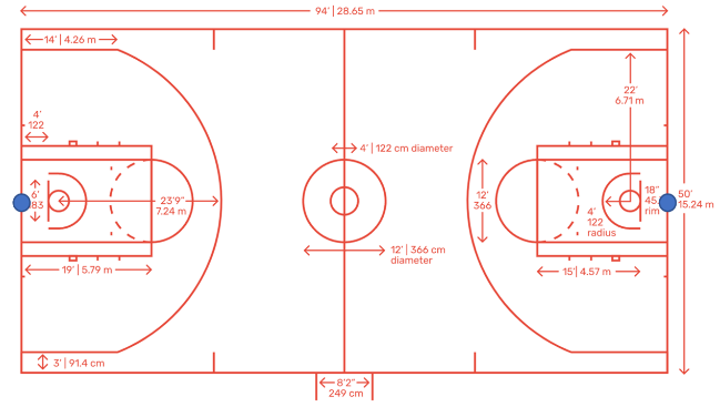
Figure 3. Camera position placement diagram.
As shown in Figure 3, two cameras are positioned at the blue dots. During the competition, the camera uploads the video to the system. The workflow of the system is divided into three major steps: identification, positioning and judgment. In the first step, the system will call the video recognition SDK to determine whether there is a basketball in the video screen and determine its position in the video (unit: pixel); in the second step, based on the known data, the system will calculate the position of the centre of the basketball in the reality (unit: mm); in the last step, the system will determine whether an interference ball violation has occurred based on the basketball's trajectory. The referee will receive a reminder when an interference violation is detected, and the referee can choose to blow the penalty directly or watch the foul clip. These three phases of the system will be discussed later in the paper.
First of all, the identification method. The system will use Hikvision's AI open platform as the training and calling port for video recognition. The platform follows the conventional training model, and the user only needs to upload the marked samples to complete the model building.
Secondly, the positioning method. In total, there are two monocular vision localization methods available. The geometric constraint method and Auxiliary measuring rod method. The geometric constraint method is based on the principle of using the geometric characteristics of a three-dimensional object projected in a two-dimensional camera coordinate system to calculate the spatial relative position of the object.
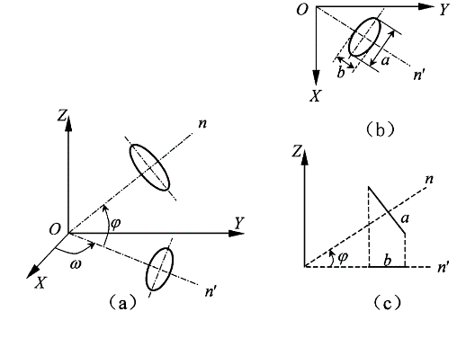
Figure 4. Schematic diagram of the principle of the geometric constraint method [7]
Figure 4 illustrates this method to find the 3D pose of the object by obtaining the elliptical projection aspect ratio of the disc-shaped object.
This method has been improved [8] to greatly improve the detection accuracy by extracting contour lines, median lines, and other line features from the images.
Table 1. Geometric constraint method accuracy rate table.
Method | Parameter | Theoretical value | With noise | Without noise | ||
measurement | error | measurement | error | |||
Ellipticity method | ω | 30 | 30.000 | 0.000 | 30.047 | 0.047 |
φ | 45 | 45.001 | 0.001 | 45.019 | 0.019 | |
Aspect ratio method | ω | 30 | 30.001 | 0.001 | 30.020 | 0.020 |
φ | 45 | 45.001 | 0.001 | 44.993 | 0.007 | |
Spiral method | κ | 60 | 60.001 | 0.001 | 59.974 | 0.026 |
As can be seen from Table 1, this method maintains very high accuracy in the absence of noise. The limitation of this method is that the two-dimensional projection of the object under test must have observable shape change under different roll angles. The two-dimensional projection of the sphere is only north-circular, so this method cannot find the unique spatial position and spatial attitude in this subject.
Principle of auxiliary measuring rod: With the help of an auxiliary measuring rod with three or more known marker points, the conversion relationship between the coordinate system of the measuring rod and the measurement coordinate system can be found by using the single image space rear meeting point. Because the coordinates of the probe of the measuring rod are known in the measuring rod coordinate system, the coordinates of the measuring point of the object in the measuring coordinate system can be obtained by coordinate conversion.
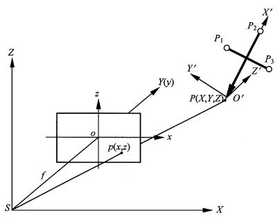
Figure 5. Schematic diagram of the principle of the auxiliary measuring rod method [9].
Figure 5 shows a schematic diagram for finding the conversion relationship between the measuring rod coordinate system and the measurement coordinate system. The linear conversion equation between the measuring rod coordinate system and the measurement coordinate system can be found point by point by using the known probe P and the relative positions of P, P1, P2, and P3. The difficulty of this method is to find the auxiliary measuring rod, while the advantage is that the camera can be observed from different angles, and only need to appear in the screen measuring rod.
4. Results
After considering previous methods, this article invented a new positioning method in basketball. The essence of positioning is the two-dimensional coordinate system in the camera screen and the real world of three-dimensional coordinate system conversion. To facilitate the calculation, the world coordinate system to the camera as the origin, the camera optical axis for the x-axis, parallel to the bottom line and perpendicular to the x-axis ray for the y-axis, vertically perpendicular to the ray of the line for the z-axis. Due to the limitations of the camera's observable range, the basketball must appear in the first and second quadrants if identified on the screen.
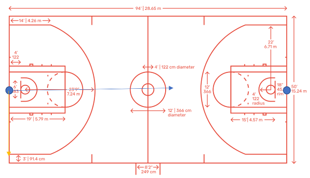
Figure 6. Top view of the real-world coordinate system.
In the illustration, the blue dot is the camera position, the blue ray is the x-axis, and the yellow ray is the y-axis
The two-dimensional image coordinate system follows the rules of the measuring stick coordinate system of the auxiliary measuring stick method, with the basket board in the picture as the auxiliary measuring stick and the bottom left endpoint of the basket board as the probe (i.e., point P). The origin of the coordinate system is point P, the bottom rays of the basket are the x-axis, and the left side rays of the basket are the y-axis.
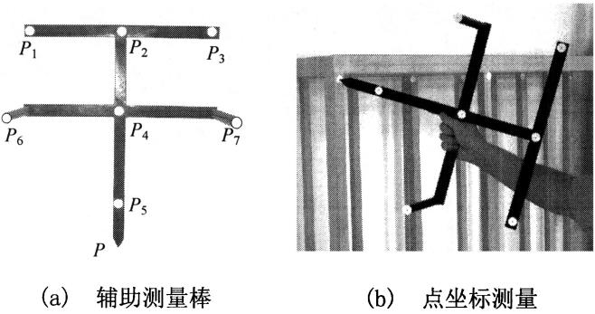
Figure 7. Auxiliary measuring rod illustration.
Figure 7 illustrates the auxiliary measuring rod. In this article, the basketball hoop could be used as the auxiliary measuring rod.
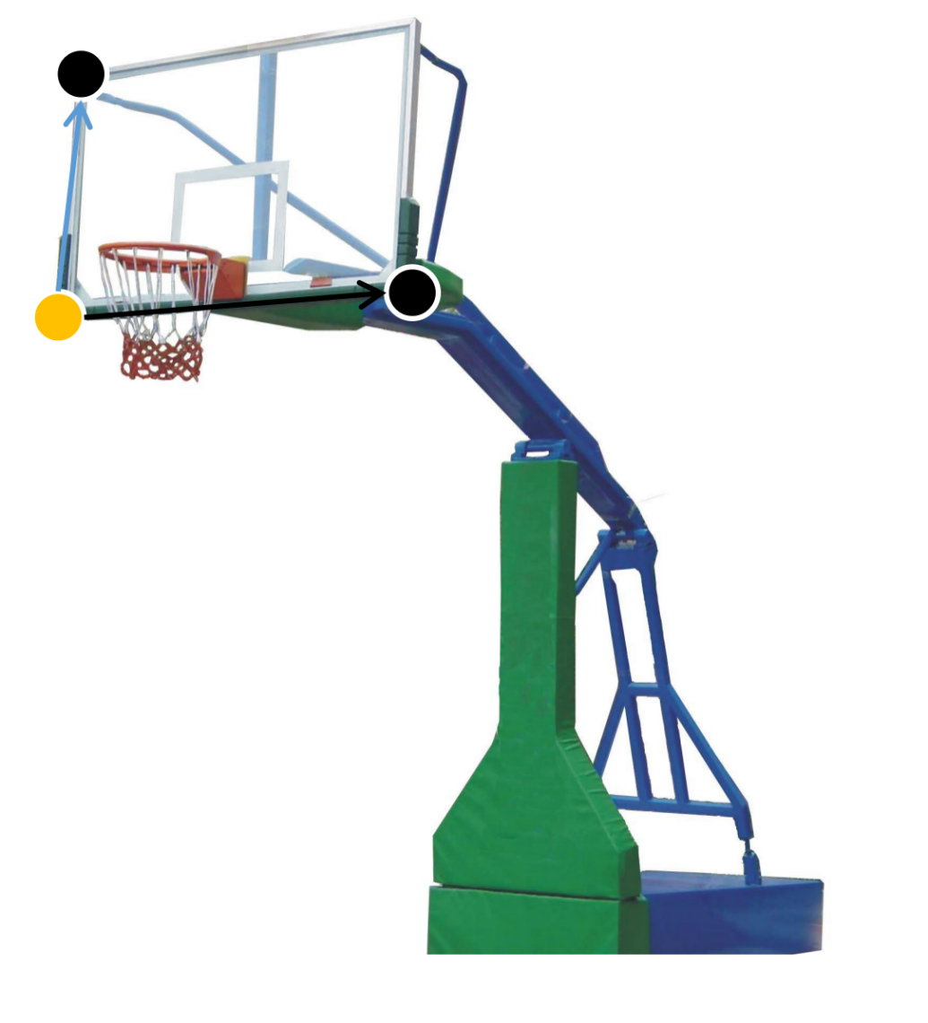
Figure 8. Schematic diagram of the camera coordinate system.
As shown in Figure 8, the yellow point in the diagram is the P point, the black point is the other rigid body point, the black ray is the x-axis and the blue is the y-axis.
The basketball is a sphere, so from any angle, the two-dimensional projection of the basketball is circular. According to the relative size ratio of the two-dimensional projection, the distance of the basketball from the camera can be found in accordance with the similar triangle theorem. The distance between the center of the basketball and the camera S1=L1*S/L can be found by the similar triangle side ratio formula, assuming that the basketball's diameter in the image is L pixels when it is centimeters away from the camera S. By ranging, the center of the basketball is fixed on a quarter sphere with the origin as the center and S1 as the radius in the three-dimensional coordinate system.
By calibrating the position of the center of the basketball, the specific position of the center of the basketball in the coordinate system of the measuring stick can be found. Since the relative position of the measuring stick (i.e. basketball board) and the camera is fixed, the three-dimensional coordinates of the projection of the center of the basketball circle on the basketball board can be found by coordinate conversion.
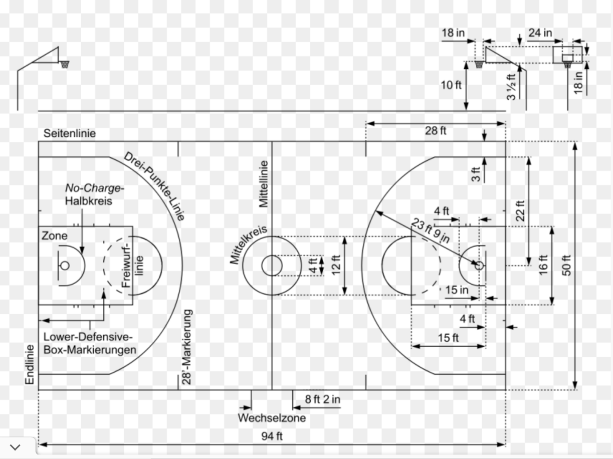
Figure 9. Standard size diagram of basketball court.
As shown in Figure 9, the standard size of the basketball court could be used to set up the initial coordinate. The camera is known as (0,0,0), then the coordinates of point P are (2680, -90,215), and the coordinates of the two rigid points are (2680,90,215) and (2680,-90,320) respectively (unit: cm). Through the coordinate system conversion formula, the three-dimensional coordinate points of the projection of the basketball circle center on the basket board can be found, set as (x,y,z). Then the center of the basketball must be on the line formed by (0,0,0) and (x,y,z).
By ranging and projecting, the position of the center of the basketball is fixed on the sphere and the line. In the first and second quadrants, there is one and only one intersection point between the sphere and the line, and this intersection point is the center of the basketball. After that, the system will judge whether a violation happens. The core idea is that in the free fall of the basketball if there is an abnormal change in the parabola, it is disturbed.
In the system operation, this step is divided into three stages: basketball speed measurement, trajectory prediction, and anomaly detection. The velocity of a basketball moving in the air can be decomposed into the sum of vectors on the x-axis, y-axis, and z-axis. The system will locate the basketball at a certain frequency, which will depend on the performance of the system. The velocity of the basketball in the three directions can be found by measuring the displacement in the three directions and deriving the displacement from the time.
In the current phase, it can be assumed that the basketball is in an oblique throwing motion after the shot. The trajectory of the basketball is estimated based on the model of the oblique throwing motion and the measured rate.
If the position of the basketball is detected to be significantly different from the predicted track, it is determined to have interference. The threshold value for track deviation will be set according to the system’s accuracy. If the center of the basketball is inside the rim cylinder, any interference with the basketball by the defender is a foul action. Therefore, the system should determine whether the basketball is in the position of the basketball ring cylinder. The three-dimensional coordinates of the basketball circle relative to the camera are known, and the three-dimensional coordinates of the basketball can determine whether the conditions are met.
If the defender interferes with the basketball during the basketball's descent, it is a violation. According to the oblique throwing motion model, whether the basketball is a downward fall can be judged based on the longitudinal velocity (i.e., z-axis velocity). If the longitudinal velocity of the basketball is negative (i.e., the vector is vertically downward) before the basketball is interfered with, the interference is a violation.
5. Conclusion
This article set up an electronic referee system based on monocular vision recognition. This system is cheaper and more convenient than other current referee systems and could be used in middle and lower-level basketball leagues.
However, there are several points in the system that could be improved in the future. First of all, the system neglects the Magnus Effect, which is an aerodynamic force yield on a spinning ball.
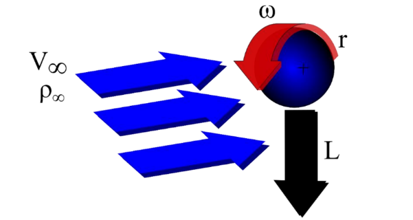
Figure 10. Illustration of the Magnus Effect [10].
As shown above, while fluid flows past a rotating ball, streamlines on the side moving in the same direction as the flow will converge, indicating a diminished pressure. The current algorithm doesn’t take this effect into consideration. On top of that, while judging violations, players may interrupt the views from the camera. Setting up cameras from different angles will solve this problem. The future study would focus on putting this system into practice. The system will be coded and tested on the basketball court to verify its practicability.