


1. Introduction
In today’s era of rapid information technology development, the widespread application and efficient operation of electronic equipment play a critical role in promoting national economic growth and advancements in science and technology. Particularly in the design of high-performance power electronic equipment, the control and suppression of leakage current have become key factors influencing the performance and safety of such devices across various industries. For instance, certain medical devices may generate resistive and capacitive leakage currents, which can pose health risks to patients [1]. Consequently, accurately measuring and effectively suppressing leakage current has become a crucial topic in the field of electronic engineering.
In the power electronics field, the impact of leakage current is especially pronounced. When the metal housing of a photovoltaic array is grounded, leakage current is generated between the parasitic capacitance and the grid[2]. This not only affects the performance and reliability of electronic components but also accelerates the aging of integrated circuits, leading to power loss and potential safety hazards [3]. The influence of leakage current is particularly significant in high-frequency, high-voltage, and high-power applications [4]. Thus, the accurate measurement and effective suppression of leakage current have become essential tasks in the design and testing of electronic devices.
|
| |
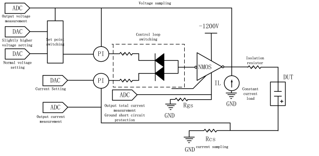
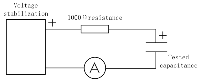
Figure 1: Polarized high-voltage source structure. | Figure 2: Direct current measurement by an ammeter. |
Currently, significant research has been devoted to the measurement and suppression methods for leakage current. On the one hand, leakage current measurement primarily relies on two methods: the capacitive leakage current measurement method, which uses a high-voltage source and current measurement module, and the indirect measurement method, which measures the voltage across a resistor. However, these existing methods have certain limitations in terms of measurement accuracy, equipment cost, and operational complexity, making it difficult to satisfy the requirements of all application scenarios. On the other hand, while techniques such as improving circuit structure and optimizing carrier modulation are considered effective strategies for suppressing leakage current, these methods still face practical challenges, such as high design complexity and increased costs.
This paper analyzes the current state of leakage current measurement and suppression technologies and primarily focuses on two main measurement methods: the capacitive leakage current measurement method using a polarized high-voltage source and current measurement module [5], and the resistive voltage method [6]. Additionally, various leakage current suppression techniques are discussed, including improvements in circuit design and optimization strategies for carrier modulation. By comparing and analyzing the advantages and disadvantages of these methods, this paper aims to provide a valuable reference for researchers and engineers working in related fields, thereby promoting further advancements in leakage current measurement and suppression technologies. Future research directions may include the development of higher-precision leakage current measurement technologies, more effective suppression methods, and applications in new electronic devices, ultimately providing technical support for achieving higher performance and more reliable electronic products.
2. Leakage current measurement
2.1. Capacitive Leakage Current Measurement Using a Polarized High-Voltage Source and Current Measurement Module
In the testing and evaluation of electronic components, the polarized high-voltage source plays an indispensable role as a highly specialized piece of equipment. It not only provides dual functions—constant current charging and constant current or constant power discharging—but also demonstrates excellent performance and accuracy in the precise control of the capacitor's charge and discharge processes.
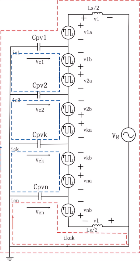
Figure 3: Single-phase PV-CMI leakage current model equivalent circuit. |
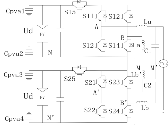
Figure 4: Single-phase cascade H5 pv inverter.
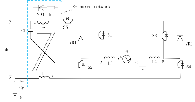
Figure 5: The novel ZPGCI topology. |
A polarized high-voltage source is a power supply device that can generate and maintain a stable high-voltage environment. As shown in figure 1, the structure of polarized high-voltage source is shown. Its core function is to enable constant current charging and constant current or constant power discharging of capacitors by accurately controlling the current flow. In figure 1, the MOS tube with high voltage and high current is generally NMOS and is required The leakage current is detected at the low end, so the negative voltage is used in the source design output. For the voltage setting, use the dual voltage set point, slightly higher The voltage set point is 2% higher than the normal voltage set point, and is used to extend the constant current charging time, Reduce the turning time from constant current to constant pressure change. When charging, first use a slightly higher voltage The setpoint control source charges the capacitor continuously when the detected charging voltage is exceeded After the normal voltage setting point, the setting point cuts the voltage setting point to the normal voltage setting Fixed point, avoid overpressure; control ring switching part will select a small control input A smooth transition from current constant current to constant pressure. In the high-pressure source output portion, add a constant-current load, The constant current load maintains the suction 1mA current throughout the measured voltage range NMOS module works in the dead zone, frequent switching leads to power ripple, same When increase the system stability. Use 100 kΩ, 1 MΩ, diode Cheng, when measuring different capacitors of different insulation levels, choose different resistors, including, diode Can play the role of variable resistance. When the source output, the pressure difference between the two ends of the diode is close On the voltage, when the current flowing through the diode is smaller, the greater the equivalent resistance, isolation The more obvious it is. Using diodes is able to cover a wide measurement range while providing short The time into the steady state. The isolation resistance in the circuit can reduce the voltage ring on the one hand The lag, increase stability, on the one hand, with the capacitance to form a low-pass filter, reduced Effect of noise on the power supply on the leakage current test.
Notably, the precise control offered by the polarized high-voltage source during charging and discharging allows for accurate measurement of the capacitor's leakage current at different voltage points. Leakage current is one of the critical indicators used to assess the performance of a capacitor, and even small changes can indicate issues such as aging, damage, or manufacturing defects. Therefore, polarized high-voltage sources are essential for detecting subtle changes in leakage current, enabling the characterization of the capacitor’s leakage current behavior across varying voltage levels. This method helps to establish the leakage current characteristic curve of the capacitor, which is crucial for evaluating its overall performance and reliability.
2.2. Indirect Measurement Using the Voltage Across a Resistor
Another common method for measuring leakage current is the indirect measurement approach, which involves measuring the voltage across a resistor. This method can be easily performed using a digital multimeter, making it suitable for the leakage current measurement of multiple electrolytic capacitors, and its structure is shown in figure 2. The digital multimeter measures the voltage at both ends of the resistor, and the leakage current is then calculated using Ohm's law, thereby enabling the measurement of the leakage current [6].
The advantages of this method include its simplicity, low cost, and the ability to measure multiple capacitors simultaneously. However, its accuracy and reliability are dependent on the choice of resistor value and the measurement precision of the digital multimeter. As a result, this method may not be sufficiently accurate for applications requiring high-precision measurements.
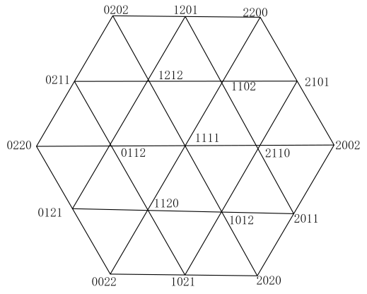
Figure 6: Distribution of common mode voltage Figure.
3. Inhibition of leakage current
3.1. Enhancing Leakage Current Suppression through Circuit Structure Improvements
In single-phase PV-CMI systems, the removal of the power-frequency transformer creates a direct electrical connection between the photovoltaic modules and the power grid. Figure 3 shows the equivalent circuit of single-phase PV-CMI leakage current model. In figure 3, Cpvi(i=1,2,..., k,..., n) indicates the i th pv assembly PVi Of the ground parasitic capacitance. Two Ls/2 are considered to consider the common mode back Road symmetric network side filter inductance. vci is the voltage of the parasitic capacitor Cpvi. The ici is the current flowing through the parasitic capacitance Cpvi. The via is left bridge arm output voltage of the HBi. The vib is right bridge arm output voltage of the HBi. The ilak is the system leakage current. When the switching device of the inverter operates, parasitic capacitance is formed between the photovoltaic module casing and the ground, leading to the generation of leakage current [7]. The leakage current of the traditional non-isolated single-phase full bridge inverter is the common-mode leakage current, while the leakage current of the single-phase PV-CMI contains not only the common-mode leakage current, but also the differential-mode leakage current. This is where the single-phase PV-CMI leakage current problem is different from other non-isolated inverters, so it is necessary to study.
To address this issue, an improved cascade H5 topology structure has been proposed, as shown in figure 4. In this structure, inductive and capacitive elements are added to the AC side for clamping and partial voltage regulation. When the inductors are properly sized, this clamp and partial voltage design can effectively suppress differential mode leakage current, allowing for control of the system's leakage current and reducing its overall magnitude [8].
In addition, a new Zero-Pole-Ground Coupling Inverter (ZPGCI) circuit was proposed in [9], as shown in figure 5. Compared to the traditional quasi-Z-source bridge GCI topology [10], the ZPGCI design reduces the size of the magnetic core, increases the value of the coupling inductance, and effectively suppresses common mode current through signal modulation and calculation.
Thus, by improving the topological structure of photovoltaic inverters, both differential mode and common mode leakage currents can be effectively suppressed.
3.2. Optimizing Leakage Current Suppression through Carrier Modulation
Traditional modulation methods [11] often struggle to maintain the stability of the common-mode voltage, making it difficult to effectively control leakage current. To address this issue, an improved three-level, three-phase, four-leg photovoltaic inverter scheme has been proposed [11]. Compared to the three-leg topology, the four-leg topology provides additional design flexibility, allowing the common-mode voltage to be fixed at VDC/2 through a specific switching strategy, thereby effectively suppressing system leakage current. However, when certain switching states of the third leg do not meet specific conditions, the switching strategy of the fourth leg may not function as intended, requiring the introduction of redundant states to replace them.
The newly proposed carrier modulation scheme enhances DC voltage utilization by combining large, medium, and small vectors. When the three-level, four-leg topology only adopts the 19 switching states shown in figure 6, the system's common-mode voltage can be stabilized at VDC/2, enabling effective control of leakage current.
To further address the issue of excessive leakage current, a novel I-DPWM (Injected Discontinuous PWM) strategy is proposed [12] . This method effectively suppresses leakage current generation [13] by parsing the injected common-mode voltage and reducing the low-frequency common-mode voltage components using the reduced common-mode voltage PWM technique. Additionally, carrier modulation is employed to generate modulation waves, which avoids the complexity of vector calculations. When the modulation index m < 0.93, the I-DPWM strategy outperforms the DPWM1 method, demonstrating significant effectiveness in suppressing low-frequency common-mode voltage and reducing leakage current.
4. Results and Future
The measurement and suppression methods of leakage current are closely interconnected. The appropriate measurement methods for high- and low-voltage environments differ significantly, each with clear advantages and disadvantages. High-voltage measurement methods provide greater accuracy and stability but are more complex and expensive, whereas low-voltage methods are more cost-effective and practical but offer lower precision.
Similarly, leakage current suppression methods follow different directions, with this paper focusing on two main approaches: improving circuit structure and optimizing carrier modulation. Both approaches are effective in suppressing leakage current, though their applications vary. For circuit structure improvements, the topological enhancement of single-phase PV-CMI systems is particularly suitable for suppressing differential mode leakage current, while the ZPGCI photovoltaic inverter is more effective for common mode current suppression.
In terms of optimized carrier modulation, the carrier modulation method for a three-level, four-leg photovoltaic inverter and the leakage current suppression method for a three-level, mid-point clamp inverter based on I-DPWM each have distinct advantages and drawbacks. The carrier modulation method of the three-level, four-leg inverter effectively stabilizes the common mode voltage, reduces leakage current, and improves DC voltage utilization by introducing additional flexibility through the extra leg. However, this method involves a more complex control strategy, which increases both design complexity and implementation cost. In contrast, the three-level, mid-point clamp inverter using I-DPWM reduces the low-frequency common mode voltage component by optimizing the modulation strategy, simplifying the control algorithm, and demonstrating more effective leakage current suppression in low-power systems. However, its effectiveness in high-power systems is relatively limited. Overall, the four-leg carrier modulation method is more suitable for scenarios requiring higher leakage current control and efficiency, while the I-DPWM method is better suited for applications where simplicity and cost-effectiveness are prioritized.
In conclusion, the measurement and suppression of leakage current are critical technologies to ensure the reliability and safety of electronic equipment. Future research directions may include developing higher precision leakage current measurement technologies, more efficient suppression methods, and applications in emerging electronic devices. As technology advances, leakage current control will continue to play a vital role in the design and testing of electronic equipment, ensuring the achievement of higher performance and more reliable electronic products and power systems.
5. Conclusion
This paper examines leakage current measurement and suppression techniques in photovoltaic (PV) inverters, focusing on improving device stability and reducing safety risks. It begins by outlining two primary measurement methods: capacitive leakage current measurement using a polarized high-voltage source and indirect measurement by tracking voltage across a resistor. The paper highlights that each method has advantages and limitations; the capacitive method is highly accurate but complex, while the indirect method is more practical and cost-effective but less precise.
For leakage current suppression, the study explores enhancements in circuit structure and carrier modulation strategies. Circuit structure improvements include a novel Zero-Pole-Ground Coupling Inverter (ZPGCI) design and an enhanced H5 topology for differential and common-mode leakage reduction. These designs integrate inductive and capacitive elements, achieving effective suppression through clamping and voltage regulation.
Additionally, the paper assesses optimized carrier modulation techniques, such as a three-level, four-leg PV inverter model, which stabilizes common-mode voltage and suppresses leakage currents efficiently. However, this method’s complexity makes it suitable mainly for high-efficiency applications. For more cost-effective, simpler implementations, the study proposes an Injected Discontinuous PWM (I-DPWM) strategy, which achieves significant leakage suppression in lower-power systems but has limitations at higher power levels.
Precise leakage current control is essential for electronic device reliability. It recommends focusing future research on higher-precision measurement technologies and more efficient suppression methods tailored for emerging electronic devices. The development of these techniques is critical to enhancing PV inverter performance, ensuring safety, and supporting long-term device stability.