


1. Introduction
The history of the automobile industry dates back to the first internal combustion engine invented in 1860. The first automobile was invented in 1886 by Karl Benz. Then, the first car produced on a large scale was called Ford Model T, and the electric strike was loaded on Cadillac in 1912 [1]. It has been really a long period for the development process of automobiles. In the latest century, the internal combustion engine is almost the absolute domination of automobiles. It was the best time for internal combustion engine automobiles in the 1950s-1960s. The enterprises especially in the USA made a quantity of full-sized cars, some even with a length of nearly 6 meters and a displacement of striking 8.2 liters, regardless of the cost, fuel economy, wind drag, or environmental friendliness. However, everything went differently in the 1970s. While the price of gasoline increased rapidly, energy became a hot spot for automobile manufacturers. The tendency to make automobiles smaller, cheaper, and consume less fuel was started by German and Japanese enterprises. Today, energy and environmental problems are becoming more urgent. An old competitor of the internal combustion engine came back again, i.e., the electric motor. It can be said that Tesla led the wave of electric automobiles. With the advantages of simpler structure, lower cost of fuel, better ability of acceleration, and some political subsidy, electric automobiles have got good graces from both enterprises and consumers. While new automobile enterprises appear one after another, traditional ones like General Motors and Volkswagen started their electrification in order to get a better place in the domain of electric automobiles as well.
Under this circumstance, automobile enterprises keep making more and more technological innovations, among which the most outstanding ones are intelligent driving systems and energy recovery and regeneration systems. There is already a relatively mature technology called the braking energy recycling system, which can be seen in a variety of electric automobiles. The basic principle is the transformation between kinetic energy, thermal energy, and electric energy, for the braking process leads to a large amount of energy loss because of the energy conversion. In terms of energy conversion in suspension systems, it is also of great significance and would save a large amount of additional energy and make great progress in the development of new energy automobiles.
This article starts from the suspension system in Section 2, including the definition and classification. After that, Section 3 is the introduction of several kinds of energy regenerative suspension. In the end, Section 4 is a simple comparison and Section 5 is the conclusion.
2. Suspension systems
2.1. definition and effect of suspension systems
The suspension system is the system that links the wheels to the unity body or frame. It carries the weight of a whole vehicle including the car body, engine, transmission, cargo, and so on. The most important parts of the suspension system are the elastic component (spring) and shock absorber. There are mainly two subsystems including the front suspension and the rear suspension. The front suspension is relatively more complex for it would move in different directions. Modern cars usually use independent front suspension systems [2].
2.2. Spring of suspension
The spring allows the suspension to deflect when it hits bumps.
2.2.1. Coil spring. The most commonly used type is the coil spring, and it is also the most traditional and ancient one. It could be compressed by the force and when the force is removed, it would go back to its original length. Its length is inversely proportional to the force, as it has a thicker coil, it is stiffer and has a higher stretching rate and rigidity.
2.2.2. Leaf spring. Leaf spring is made of flat and long metal, a few of them in different lengths stacking together. The bolts that connect the spring to the frame have rubber bushings, which means they can also absorb vibrations, and then additional shock absorber is not needed. The new technology of composite material is the type of lightweight design in leaf spring, which has a lighter weight but a higher strength, it is about 50% lighter than pure steel type [3].
2.2.3. Torsion bar spring. Another type which is also the simplest one is called torsion bar spring, which could absorb force by twisting. It is easy to adjust for the height of the vehicle but is mainly used on heavy vehicles like tractors and tanks. It can also be seen under the seats of vehicles, especially the off-road ones [4].
2.2.4. Air spring. Air suspension is a new type of system, mainly used on heavy trucks and limousines. Their springs could be divided into bellows-type air springs, sleeve-type air springs, and diaphragm-type air springs. They are expensive but make it possible to lift or lower the vehicles, absorb vibration better, and provide higher quality of driving [5].
2.3. Types of suspension systems
The most common structural components of the suspension system include (single or double) transversal type suspension and trailing arm suspension, Macpherson suspension, single oblique arm type suspension, and multi-link suspension [6].
3. Energy regenerative suspension
3.1. Necessity of regenerative suspension
As an automobile drives on a catering surface, the wheels would run over innumerable small pits and humps, which means the length of the suspension system would change constantly. In addition, when an automobile turns a corner, the weighted core moves left to right. On the other hand, if it is accelerating, the front suspension extends as the rear suspension compresses; while braking, things go oppositely. All the circumstances mentioned above can lead to persistent vibration in automobiles. The vibrations mean the stretch of the suspension system and the change of kinetic energy. In a nutshell, the vibration absorber is designed to convert kinetic energy into thermal energy in order to reduce the influence of vibration and provide a better drive experience. However, the thermal energy would not only affect the performance of the suspension but also spread into the air by heat loss. Above all, drivers are reluctant to have a bad driving experience or waste this energy. But if automobiles can store and reuse thermal energy, these problems would be all solved, and that is why the energy regenerative suspension system was invented.
3.2. Classification of energy recovery and regeneration systems
Figure 1 is the block diagram of energy regenerative suspension, illustrating the working principle.
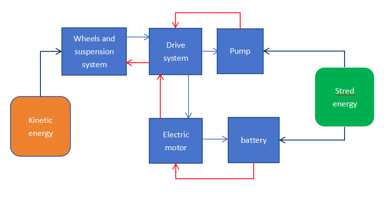
Figure 1. The block diagram of energy regenerative suspension
3.2.1. Principle and structure of hydraulic energy recycling system. The key part of a hydraulic energy recovery and regeneration system is the oil hydraulic pump. Here the coil spring-type suspension system is used as an example for it is the most popular one at present. There are two ways to turn the energy of vibration into the internal energy of compressed oil. One is to set a hydraulic cylinder on each wheel axle. In this case, the cylinder should be connected to the axle on one end and the other with the chassis, which should be parallel with the coil spring and the vibration absorber, or even probably takes the place of the absorber. The cylinder will work as the spring is stretching, and energy will float into the hydraulic pump through a one-way clutch, which might take place by unilateral bearing now [7]. Another method is to use a set of gears, including planetary gear and worm gear to change the reciprocation into rotation to make the energy easier to recycle by the pump. That would not need these cylinders but the efficiency of the gears set is relatively lower.
When the driver pushes down the accelerator pedal, this signal is sent to the control system, and then an order is delivered to the hydraulic accumulator, to release the high-pressure oil. The high-pressure accumulator will let the oil out and then float into the pump. The torque provided by the pump transfers through the transmission, drive shaft, retarder, and finally the driving wheels. If it is an electric automobile, it is possible to use a hydraulic motor. When it works, a coupler can transfer the energy to the electric motor [8].
Lu Fashuai et al. from Taiyuan University of Technology conducted correlative research and design. They built a mathematical model based on Gaussian white noise theory in order to simulate the random surface of the road. After the calculation of the suspension model and the velocity characteristics of the vibration absorber, they chose a heavy truck as an experiment inside the school. The experiment proceeded on concrete pavement with speed bumps, the length was 300 meters and the velocity of the vehicle was 30 km/h. During this experiment, the peak displacement of suspension was 10.44 mm, the maximum speed was 0.48 m/s, and the maximum power of the vibration absorber reached 1310.6 W. A kilo-watt class dissipation makes it significant to load an energy recycling system. They chose a hydraulic cylinder with a diameter of 30 mm which could produce a force from 1000-2800 N. The motor was a BMM8 type-cycloid hydraulic motor with a power of 1.3 kW and a torque of 8 Nm. A NXQ air bag accumulator works for the storing. Finally, they used the data from the experiment in the simulation and accomplished a complete work system [9].
3.2.2. Principle and structure of air-pressure energy recycling system. This type of recovery and regeneration system is more suitable for automobiles with air suspension. The main principle is similar to a hydraulic energy recycling system, but a pneumatic accumulator is applied instead of a hydraulic accumulator. The accumulator is, in fact, a kind of airbag, so if this is loaded on an automobile with air suspension, it can be linked with the air spring.
When the driver pushes down the accelerator pedal, the control would give the same response as the hydraulic one. There would be an air motor to do the same things as well, generating torque and being transferred to the driving wheel. However, the power of an air motor would probably be lower than that of a hydraulic motor. Under this circumstance, there is another way to reuse the energy. In the case of an internal combustion engine automobile with a turbo or two, the air with high pressure can be gushed into the turbocharger together with exhausted gas. Then it would provide extra power for the automobile, because the air with high temperature and pressure, just like exhausted gas, is especially suitable for turbochargers [10].
Some power stations use compressed air for energy recovery, like the Huntorf power station (1978) in Germany and the Mclntosh power station in the USA (1991). According to the research of Wu Bin and his team, the basic theory is using the air with high pressure to drive the gas turbine. The air-pressure energy recycle system is possible to be seen in domains of stabilizer with safely operating electric system; adapter of high voltage transmission; optimizer for the power grid of new type energy and iterator of the transformation of thermal power plants. Unfortunately, it is seldom used for small-volume equipment. They point out that the main risk is the uncertainty of investment [11].
3.2.3. Principle and structure of electric energy recycling system. An electric energy recovery and regeneration system mainly includes an electric accumulator or a set of energy storage batteries, an appropriate electric motor, and a corollary transmission system. This type of energy recycling system is more suitable for electric automobiles, for there are already an electric motor and a battery pack on the automobile, so there would be no need for additional electric element. That means these automobiles’ energy feedback suspension would cost much less. The principle is similar to the electric braking energy recovery system, which has been used in some kinds of electric cars. Part of the kinetic energy would be lost by heat, the others would float through an electric motor, then alternating current (AC)/direct current (DC) converter, DC/DC converter, and finally be stored in the battery [12].
When the driver pushes down the accelerator pedal, the electric motor produces torque which is finally transferred to the driving wheels. In this circumstance, energy in the battery which is recovered from vibration can be reused. This is feasible for both electric automobiles and hybrid automobiles, including plug-in hybrid and extended-range engines, but not practical on automobiles without electric motors. In fact, in internal combustion engine automobiles, a compressor can solve this problem. Being different from the exhaust gas turbocharge type automobiles which usually produce a relatively low torque at a slow speed of revolution, an electric supercharging system could perform much better with the help of a high-speed electric motor. They are divided into e-turbo and e-booster. E-turbo is a combination of an electric motor and a traditional exhaust gas turbo, rotors of the motor and turbo are coupled together. E-booster means the electric motor is connected to an additional compressor and transfer torque to it, which blow air at high speed and pressure into the turbo [13].
Han Sen et al. from Chongqing Jiaotong University designed and simulated a multifunction energy regenerative suspension control system with a linear electromagnetic actuator. Without the structure of excitation, an electric motor with a permanent magnet has a higher power density and efficiency. They chose Macpherson suspension as an example and built up a model of a suspension system with two degrees of freedom. The PSD (pavement power spectral density) is an ideal target to reflect the relation between automobiles and the surface of the roads. The performance index of the electric recycling suspension system includes the smoothness of the ride and the capacity usage ratio. They designed a complete control system and made the simulation of the mathematical model of the sub-systems [14].
3.2.4. Principle and structure of mechanical energy recycling system. The mechanical energy recovery and regeneration system is mainly based on flywheel. The flywheel-type accumulation system was first designed to keep the running smoothness of the internal combustion engine as a regulating element. In the 1950s, they were used as mechanical energy accumulation devices but were hard to be loaded onto automobiles because of their weight and volume. Until the 1990s, the flywheel-type dynamical system for vehicles appeared gradually, known as the flywheel-type auxiliary power unit [15].
When the driver pushes down the accelerator pedal, the flywheel releases the energy and transfers the torque into a transmission, drive shaft, retarder, and finally the driving wheels. Or there could be an electric motor driven by the flywheel, and the following principle is similar to that of an electric type energy recovery and regeneration system. Flywheel-type accumulation is also called electromechanical cell or flywheel battery. In general, it is a kind of equipment that can accomplish the reversible transform between kinetic energy and electric energy or reserve electric energy and output kinetic energy [16]. To some degree, it is just a special type of battery.
Fan Zhanquan et al. conducted research on the application of flywheel energy storage technology on emergency power supply vehicles. His company designed a power van with a flywheel energy storage system with a power of 200 kW, a diesel engine with a power of 300 kW, a power unit, a power distribution unit, and a monitoring software system. In early 2022, their production was officially devoted to running, and they took part in several exhibitions and activities [17].
4. Comparison of energy recycling systems
4.1. Simple comparison
Here is a simple comparison among these four types of energy recycling systems. As shown in Table 1, it is divided into several variates.
Table 1. Comparison of types
Types | Hydraulic | Air pressure | Electric | Mechanical |
Technical maturity | High | Low | High | Medium |
Lifetime | Long | Low | Medium | High |
Stability (temperature resistance) | Low | Extremely low | Medium | High |
Cost | High | High | Low | Medium |
Environmental friendliness | Medium | High | Low | Medium |
4.2. Characteristics of different types
4.2.1. Hydraulic energy recovery and regenerative system. Hydraulic energy recycling system is a kind of mature technology, which has a long life and they are convenient for different kinds of power forms on automobiles. Either the direct use of the energy from liquid pressure or setting an additional hydraulic motor could provide extra torque for driving wheels and accomplish the recycling of energy. Except for a relatively high cost, there is no obvious shortcoming of it.
4.2.2. Air-pressure energy recovery and regenerative system. Air-pressure energy recycling system is mostly at the stage of theory and experiment and there is not enough technical support yet. In addition, it has the largest amount of disadvantages in the four types such as it is short-lived and unstable. It also has a lower energy density and costs a lot. So except for being environmentally friendly, it is not a good choice, or at least not for now.
4.2.3. Electric energy recovery and regenerative system. Electric energy recycling system is also a mature technology. Benefiting from the rapid development of electric braking energy recovery and regeneration systems, this technology has received a large amount of data from experiments and feedback from the market. The most obvious shortage is the pollution of batteries, but this is also inevitable in the production of electric automobiles. It is especially ideal for electric vehicles, while for internal combustion engine type ones, an additional compressor can solve the problem, which is not an unacceptable addition.
4.2.4. Mechanical energy recovery and regenerative system. A mechanical energy recycling system can be described as a special kind of electric energy recycling system, with a longer life and better stability, though it is a bit more complex and costs a bit more. However, the shortage of enough experiments makes it a little unreliable to the consumers. This can be understood, and as such a new type of technology, it still has a long way to go and the opportunity to be widely used.
5. Conclusion
As automobile enterprises all focusing on energy conservation and emission reduction becomes a trend, the energy regenerative suspension system is a significant application in both the economy and the environment. Unlike the braking energy recovery and regeneration system which involves driving safety, there is little concern about the risk of the practical application in terms of the research on energy regenerative suspension systems. As a new technology, there are no practical and commercialized applications at the moment. However, researchers in all professions have started their attempts at the research. While the air pressure type recycling suspension system has some relatively obvious shortcomings and is the most immature one, the other three types of recycling suspension systems all have the opportunity of being used widely in the market, especially the electric type and the hydraulic type that have the applications in the braking energy regenerative system. Benefiting from their principles and theories, the cost of money, work, and time of the design and development process would be greatly shortened. It is not hard to see that the energy regenerative suspension system has a considerable development prospect. Additionally, after some more researches and experiments, it would become a new focal point of the automobile industry.