

1. Introduction
The domain of FPGA-based (Field Programmable Gate Array)image recognition is currently advancing through the integration of deep learning and real-time processing, leading to heightened precision and efficiency. Additionally, this integration is broadening the scope of its applicability. In the context of gesture recognition, FPGA technology is being employed to augment human-computer interaction. Through the utilization of FPGA’s parallel processing capabilities, real-time and efficient recognition of gestures is achieved, thereby enhancing the overall interface experience.
This paper’s experiment focuses on utilizing the Verilog programming language to implement basic image processing and recognition. It further involves orchestrating the lower-level system to perform corresponding language synthesis for the identified outcomes. The compilation environment centers primarily on Quartus and Keil platforms. The fundamental model is constructed employing the DE2-115 development board, a 51 microcontroller, and the MAX232 serial port chip.
The overall process is shown in Figure 1.
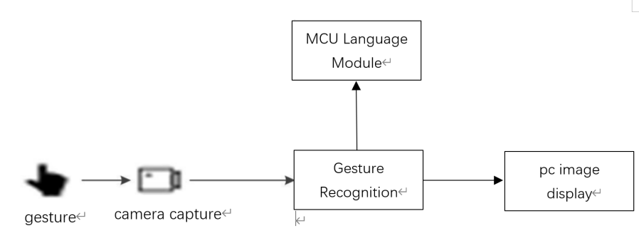
Figure 1. Overall process.
This experiment’s significance lies in demonstrating the practicality of using Verilog for FPGA-based image processing and recognition. It integrates lower-level control and language synthesis for comprehensive gesture recognition. Leveraging Quartus, Keil, and standard hardware like DE2-115 board, 51 microcontroller, and MAX232 chip, the study contributes practically to gesture recognition. It connects hardware design with software synthesis, shedding light on FPGA’s potential for real-time image processing and interactive applications.
2. Methodology
2.1. Performance indicators
Before the implementation of this thesis project, the basic performance requirements to be achieved by the following projects are established.
Hardware Performance Metrics:
a. The hardware system must reliably provide power to all board components via its USB port. Upon connection to a computer, the USB port should be promptly recognized as a serial communication interface, facilitating seamless program downloads. Furthermore, the microcontroller should proficiently accommodate and execute the downloaded programs.
b. The hardware architecture should demonstrate proficiency in receiving messages from the FPGA terminal through the DB9 serial port. These messages should be efficiently relayed to the microcontroller’s register via the max232 chip. Upon reception, the microcontroller should adeptly manage the output of relevant information through its IO ports, thereby regulating voice broadcast control.
c. Activation of the microcontroller-associated reset button should promptly and reliably cease voice playback operations.
Software Performance Metrics:
The software algorithm must effectively and accurately segment, recognize, and convey signals corresponding to gestures. Moreover, the visual representation of images must maintain a superior level of clarity, ensuring the fidelity of the conveyed information.
2.2. Development platforms
In the FPGA segment, Verilog serves as the primary programming language and is executed on the Quartus platform. The VGA video signal is linked to the display screen, facilitating convenient debugging.
For the microcontroller segment, programming is primarily executed in C language using Keil. After compilation, the files are burned onto the development board or a self-designed circuit board using programming software to verify the functionality. Concerning serial communication, initial debugging involves interaction between the microcontroller and PC-based serial debugging tools to ensure accurate signal transmission and feedback.
Regarding hardware design, the Altium Designer (referred to as AD) is employed. Within AD20, the schematic diagram for the PCB is created, followed by importing the PCB component library and assigning package styles to components. Subsequently, the schematic diagram is transferred to the PCB layout. Components are positioned on the PCB board, followed by processes such as routing, copper pours, and solder mask application.
2.3. Hardware overall plan
The hardware design involves utilizing a 51 microcontroller to control the speech module for audio playback. Simultaneously, the microcontroller’s TXD and RXD pins receive signals from the FPGA, which are then converted using the MAX232 chip. Additionally, a USB download circuit is designed on the board to facilitate program downloading to the microcontroller via the USB interface, which also serves as the power source for the entire circuit. The schematic diagram is presented below, see Figure 2 for reference.
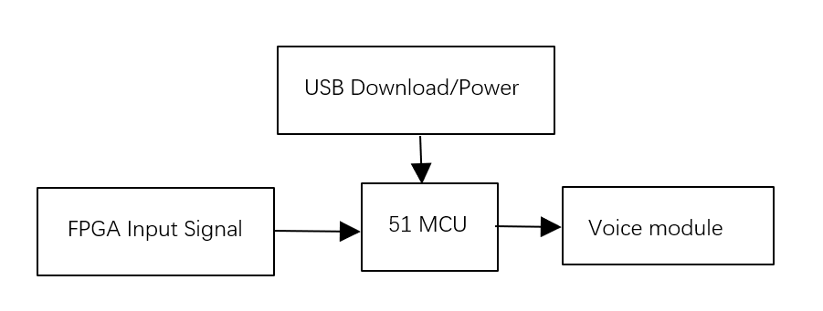
Figure 2. Hardware overall plan.
3. FPGA design
3.1. FPGA for gesture recognition
The whole process for FPGA to deal with the figure follows the steps Figure 3 illustrates. In the image recognition process, we start with median filtering to reduce noise and preserve edges. Then, skin color detection is performed to segment skin and non-skin regions. Next, dilation expands the skin regions, followed by erosion to remove noise. Edge detection identifies abrupt changes in intensity or color. The processed image is displayed for visual inspection. Finally, pixel comparison based on lines helps detect patterns or features not evident from individual pixels. This workflow involves median filtering, skin color detection, dilation, erosion, edge detection, image display, and pixel comparison based on lines.
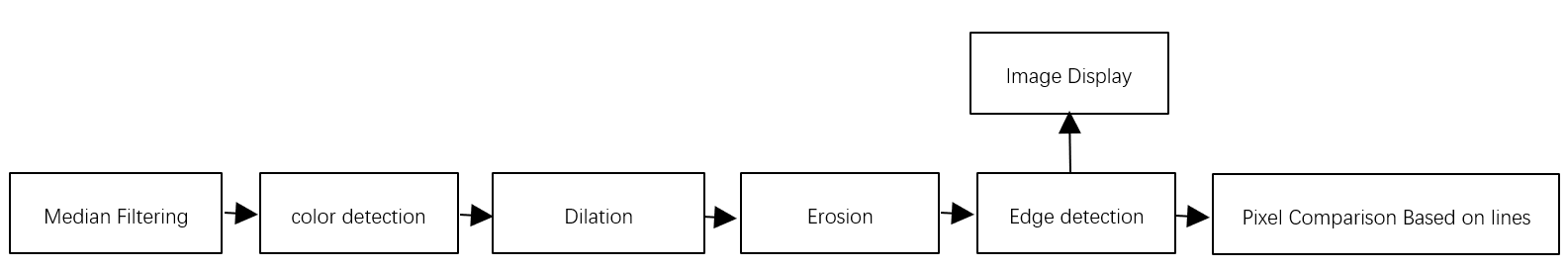
Figure 3. FPGA for gesture recognition.
3.1.1. Median filtering. Prior to subsequent processing, like edge detection, an initial noise which is effective only for low one reduction phase is conducted [1-2]. RGB input pixels undergo rapid median filtering, with the resulting medians then employed for skin tone detection.
In the context of input RGB pixels, an initial step entails generating a 3x3 matrix. The manipulation of this matrix is executed using shift registers within the IP core. This procedure caters to the manipulation of 800x600x8-bit image data, with a specified width of 800 and the establishment of two fixed intervals for the outputs of the shift registers, both spanning 8 bits. Consequently, the ultimate output encompasses the last bits of two rows, each encompassing 800 pixel points.
Subsequent phases involve invoking predefined functions, including max, med, and min [3-4]. This facilitates the computation of the median grayscale value within a 3x3 sliding window encompassing a designated central pixel. The resulting median value then becomes the definitive value of the central pixel.
Furthermore, the sliding window progressively shifts column by column to the left. The final output encapsulates the culmination of median filtering. Moreover, a dynamic aspect is introduced through the utilization of the FPGA board’s switch mechanism. This mechanism governs the discretion of executing the median filtering operation, enhancing operational flexibility.
3.1.2. Skin color detection. The algorithm employed for skin color detection initiates by converting the input RGB values into the YCbCr color space utilizing the following equations. This procedure incorporates multipliers with parameters configured at bit widths of 8-17-27.
Y << 10 = (12’h107 * R) + (12’h204 * G) + (12’h064 * B) + 20’h04000;
Cr << 10 = (12’h1C2 * R) + (12’hE87 * G) + (12’hFB7 * B) + 20’h20000;
Cb << 10 = (12’hF68 * R) + (12’hED6 * G) + (12’h1C2 * B) + 20’h20000;
The YCbCr color space is a widely adopted color model in the domain of skin color detection. In this model, Y corresponds to luminance, Cr signifies the red chrominance component with respect to the light source, and Cb represents the blue chrominance component with respect to the same light source.
Subsequently, by imposing upper and lower limits on the R and B values within the respective intervals of 532-692 and 308-508, the algorithm isolates the skin region. Notably, the selection was made to regulate the grayscale value display of the skin color detection area through switch mechanisms integrated into the FPGA board. When the switch is activated, the skin color detection region is depicted in a monochromatic black hue. Conversely, when the switch is deactivated, the display is confined to an edge-enhanced rendering.
3.1.3. Dilation. Before conducting the dilation process, as the dilation algorithm requires a 3x3 matrix as input, the grayscale values obtained from the skin color detection output are transformed. Dilation is a procedure that merges background points adjacent to the object with that object, causing the object’s boundary to expand outward. This is achieved through the following computational formula:
P = P11 | P12 | P13 | P21 | P22 | P23 | P31 | P32 | P33(1)
Moreover, an additional switch has been introduced to control the dilation operation. In order to enhance the dilation effect, we have implemented four consecutive dilation stages.
3.1.4. Erosion. Erosion is a process that eliminates boundary points and causes the boundary to contract inwards. It can be utilized to remove small and insignificant objects. This is achieved through the following computational formula:
P = P11 & P12 & P13 & P21 & P22 & P23 & P31 & P32 & P33(2)
Additionally, a switch has been introduced to control the erosion process. To enhance the erosion effect, we have implemented four consecutive erosion stages.
3.1.5. Edge detection. The edge detection process starts by converting the output grayscale values into a 3x3 matrix. Subsequently, evaluate the effectiveness of the 3x3 matrix using the following formula:
P=P11&P12&P13&P21&P22&P23&P31&P32&P33 (3)
If the result is 1, it means that the surrounding pixels in the region have the same value, indicating that the region is not an edge. The edge is represented by a value of 0. Non-edge areas are designated to be displayed in white, while edge areas are displayed in black.
In this way, the process identifies edges by checking the consistency of adjacent pixel values, and uses thresholds to distinguish between edge and non-edge regions. Edge detection is a basic technique used to detect boundaries and important features within an image.
3.1.6. Image display. For accurate identification, a 250x250 frame is introduced and centered within the image. Row synchronization and frame synchronization are calculated based on the rising edges of row synchronization signals or falling edges of reset signals. These values are used to constrain the frame’s dimensions.
Within the frame, calculations involving pixel values ensure the distinction between the frame’s interior and exterior. Columns and rows are determined similarly. Operations such as edge detection and skin color detection occur within the frame’s interior.
Inside the frame, processed grayscale values are converted to RGB for display. If the grayscale value is 0, it’s displayed as black; otherwise, it defaults to white. This process employs synchronization signals and calculated boundaries to facilitate operations within the designated frame, leading to an accurate display of features and information.
3.1.7. Pixel comparison based on lines. Similar to perimeter and area calculations, the process is akin, but with the addition of a field synchronization signal to determine if it’s in proximity to the center of the image. This, in turn, allows assessment of the number of black pixels within a designated area, enabling the output of finger count. For instance, if there’s one finger, there would be two black pixels above and below.
In essence, this procedure utilizes the field synchronization signal to ascertain the central image region and then quantifies the black pixels within that area to deduce the finger count.
3.2. FPGA communication module section
3.2.1. uart_top top-level module. This module establishes foundational parameters and sets the baud rate to 4800. It calculates the number of system clock cycles per unit bit time based on the configured baud rate and the existing system clock frequency. It interfaces with the uart_send module. Generally speaking, uart will have two parts: one to send and the other to receive [5]. However, in this project, as the upper computer of the FPGA, only data needs to be sent, so at the top level, only the transmission module needs to be mapped.
3.2.2. uart_send module. To enable continuous transmission and reception signals, the sending enable within this module is set to 1. Signals received from the gesture recognition module are stored in the uart_din register. To comply with UART communication protocols, the outputs are assigned using non-blocking bitwise assignments. Starting with the 8-bit data in the uart_din register, a ‘0’ start bit and a high-level ‘1’ stop bit are added.
4. System testing and result analysis
4.1. Software debugging process
By stabilizing gestures, adjust the surrounding background and brightness. Items with reduced background and similar skin color. Then, after the camera captures good gesture images, the gesture recognition results are output and displayed using signaltap and digital tube. For example, gesture 1 can output “0F1H” in signaltap. If “1” is displayed on the digital tube, it indicates successful debugging.
4.2. Hardware debugging process
First of all, debug the USB download circuit: use the computer’s serial port debugging assistant to send information to the board through the USB port to see if the voice module can work normally. Then use the serial port debugging assistant to send information to the board through the DB9 port to see whether the max232 chip can work normally, and whether the microcontroller can receive messages normally.
As shown in Figure 4, The images show the signal tested by Signaltap that are (a)0xF1H, (b)0xF2H, (c)0xf3, (d)0xf4 and the images of gesture.
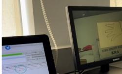
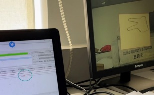
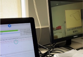
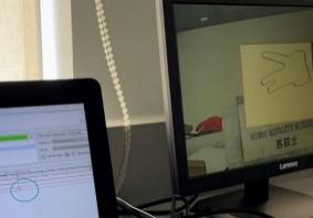 (a) (b) (c) (d)
Figure 4. Experiment result, (a)0xF1H, (b)0xF2H, (c)0xf3, (d)0xf4.
5. Conclusion
This thesis experiment tries to use FPGA gesture recognition with speech broadcasting. The use of Pixel Comparison Based on Lines is able to recognize gestures on top of FPGA with good timeliness, but at the same time the requirements for ambient light are high because no more advanced algorithms were used, the recognition code was written relatively simply. So, it is inevitable that there is a certain probability that the system will misreport information.
There are also more areas for improvement in this experiment: Firstly, the image processing part of the Verilog compiled algorithm is more basic, if the use of the area and perimeter contrast algorithm will be better, there is a certain degree of difficulty in implementation for the test environment and conditions are more demanding, the need to stabilize the degree of illumination and man-machine test distance. Secondly, the experimental gesture samples are still too few, so the generalization of the project compiled during this experiment is low.
In the future, Research can be conducted to learn operators and try using Verilog to rewrite some operators, like Canny operator which is effective in traditional edge detection algorithms and morphological operators for example, to enhance the treatment of dilation and erosion.