

1. Introduction
RISC-V adheres to the principles of reduced instruction set architecture and operates as an open-source instruction set [1]. It stands as a fully accessible instruction set, available for utilization by both individuals and companies without any associated costs [2]. It was developed by a team led by Professor David Patterson at the University of California, Berkeley, and has since become a strong new force in RISC processors [1]. RISC-V instruction set architecture has the advantages of low power consumption, low cost, small area, and high speed [3]. This open standard Instruction Set Architecture is intended to facilitate 32-bit, 64-bit, and 128-bit address spaces. It has been designed following the principles of a Reduced Instruction Set Computer (RISC) [4].
This paper focused on RV32I, which refers to the 32-bit base integer instruction set. This paper divides a RISC-V instruction into five stages, adds registers to implement a five-level pipeline structure, and gives the simulation results of some instructions, such as addi, slli, jalr, etc. In the RISC-V pipeline structure, there will be a variety of hazard problems, and three categories of hazard: structural hazard, control hazard, and data hazard [5]. For some examples of these three types of hazards, this paper uses the method of adding registers to give solutions, simulation results, and feasibility analysis respectively. This paper presents several effective methods to solve the RISC-V pipeline hazard problem, which can ensure the efficient and stable operation of the RISC-V processor in the five-level pipeline structure [6].
2. RISC-V instruction set
RISC-V constitutes a liberated and openly accessible Instruction Set Architecture (ISA), fostering a fresh era of processor advancements facilitated by collaborative efforts concentrated around open standards. RISC-V ISA architecturally provides a new level of free, scalable software and hardware freedom [6, 7]. The instruction set of RISC-V consists of two parts: basic instructions and extended instructions [8]. According to the different register bit width and address, it is divided into 32, 64, and 128 three different instruction sets. This paper focuses on the 32-bit wide rv32i, for applications that need more speed while using less electricity [4]. Because of their simpler instructions and less reliance on them, RISC-based computers may be the best choice for pipelined instruction execution [9]. Any processor's basic architecture is improved by pipelining since it increases speed, throughput, and performance. While a pipeline is executing an instruction, the following instruction can be processed concurrently without interfering with the completion of the ongoing instruction, thereby enhancing overall processing speed [10]. However, the potential for data and control hazards leading to pipeline stalls represents the primary downside of utilizing pipelining [6]. This study describes a 32-bit RISC-V pipelined processor architecture that uses approaches for hazard removal including branch prediction and data forwarding [1].
3. Five-level pipeline design
Single-cycle CPU executes a complete instruction in one cycle, takes the instruction when the clock rises, decodes, executes, and accesses it during the high-level period, and writes it back when the clock falls [4]. The five-level pipeline only completes one stage in one cycle. With fewer tasks to complete, fewer circuit modules are needed, the execution time is short, and the processor can have higher frequencies [11]. Five-level pipeline, as the name suggests, a total of single-cycle instructions are divided into five stages: fetch instruction, decode, execute, access memory, and write back, so the final generation is a five-level pipeline, at most five instructions can be processed in parallel [12]. While instruction 1 is executing, instruction 2 is already decoding. However, each level is independent, and to ensure that instruction is executed correctly, it is necessary to do a good job of interacting with each level (if you can avoid some interactions, naturally, it is excellent). For example, instruction 1 is the ADD instruction. When instruction 1 goes through the write-back cycle, data needs to be written back to memory rd. At this time, the rd output by Decode is the rd of instruction 4, which results in an error. Therefore, in the decoding cycle of instruction 1, it is necessary to put the rd of instruction 1 into the register and take it out when the write-back cycle is used. If you want to implement pipeline structure, you need to use registers and shift registers to complete such operations.
4. The solution to several hazard problems
Pipeline hazard is the issue that the pipeline mechanism creates when the subsequent instruction cannot be implemented correctly in the subsequent cycle. Pipeline hazards may be broadly classified into the following three types:
4.1. Structure hazard
The pipeline structure we designed will not currently be subject to the structural hazard that arises when the hardware cannot handle multiple instructions running concurrently owing to hardware conflict issues.
The receive and delay registers' primary job is to clock the input data up and the output data down. The receive register fetches the input data while the delay register stores the output data. To recover input data that has been shelved for several cycles, use shift's shift register.
When two instructions separated by three cycles are carried out at the same time, one instruction is in the fetch instruction stage, and the other instruction is in the memory access stage, both stages need to exchange the data of the register with the memory, and only one memory is prone to errors when the data is called. Storing instructions in RAM and data in ROM can effectively avoid this structural hazard. The code for the top-level file is shown in Figure 1.
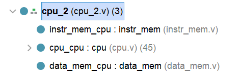
Figure 1. Top-level file code (Photo/Picture credit: Original).
4.2. Control hazard
Control hazard occurs when conditional branch instructions are encountered. Since the jump condition is only known during execution, the pipeline must halt or wash instructions for the pipeline to function properly.
When the control hazard is encountered, such as using the method of assuming that the branch does not occur when the branch jump occurs, it is necessary to wash away the redundant instructions, and enable the rise edge reading jump in period 3 to achieve the following control: All the control signals generated by instruction 2 in period 2 are cleared to zero, to achieve the purpose of washing the pipeline. Change the address read by the PC to achieve the purpose of jumping.
4.3. Data hazard
Data hazards may arise due to the overlap of the destination register of the preceding instruction and the source register of the subsequent instruction, leading to potential data conflicts. The provided simulation employs the instructions illustrated in Figure 2 to exemplify three possible scenarios of such data conflicts.
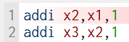
Figure 2. Two instructions that can lead to data hazards (Photo/Picture credit: Original).
4.3.1. When two instructions are separated by one cycle
In the pipeline system, data hazard happens when the value of the previous instruction's target register is used and the execution result of an instruction has not yet been written back to the register [4]. When the second instruction is in the decoding phase, it needs to read the value of register X1, but at this time the first instruction is in the execution phase, according to the normal pipeline schedule, it needs to wait until the fifth cycle to write back the result of X1. Therefore, the value of X1 read out at this time is the old value, which is the wrong situation.
In this case, the method is to add a selection in the ex-module, and the selection signal is generated by the register comparison. When it is judged that the current operand storage address is the same as the destination operand register address of the last time, the output of ALU is directly used as the input of this operation ALU.
The specific solution code is as follows: by comparing the value of the second instruction rs1 with the value of the first instruction rd, the final determination of the ALU output value is what, if the two registers have the same address, the ALU output value of the first instruction is directly assigned to the input of the second instruction.
4.3.2. When the two instructions are separated by two cycles
At the end of the first instruction retrieval phase (the end of the fourth cycle), the result of the X1 to be written back is passed to the beginning of the execution phase of the third instruction (the beginning of the fifth cycle). The register of the delay rs1 used earlier here can be used again, and what needs to be modified is to add shift_n as the shift registers for clock falling edge control, and shift function as the shift registers for clock rising edge control. In this case, add data_out_s_2 and rd_jud_2 to the ALU module to solve the problem.
4.3.3. When two instructions are separated by three cycles
Although the first instruction has entered the write-back phase, it has not yet fully written the result of register X1 back to the register, and may still be "on the way" to write back. This is where the data hazard happens.
4.3.4. ALU module
This paper introduces three additional enable signals. When the current instruction's source register matches the destination register from one, two, and three cycles ago, the corresponding enable signals are set to 1 for each respective case. When the enable signal is judged to be 1, the value of the destination register of the previous instructions is directly input into the ALU module of the current instruction.
5. Validation testing and analysis
5.1. Pipeline structure and structural hazard and control hazard testing and analysis
The instructions used in the simulation are shown in Figure 3, including the instructions of RV32I of types R, I, B, and J.
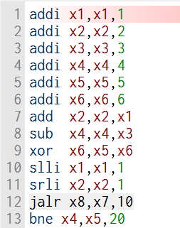
Figure 3. Part of the instruction used to test the pipeline structure (Photo/Picture credit: Original).
As shown in the figure below, this paper has selected some common instructions, including the non-conditional jump instruction and the conditional jump instruction (jarl, bne), where control hazards occur. In the selection of these instructions, a specific selection of registers circumvents the possibility of data hazard. Its simulation results are shown in the figure. The results of the simulation are shown in Figure 4.
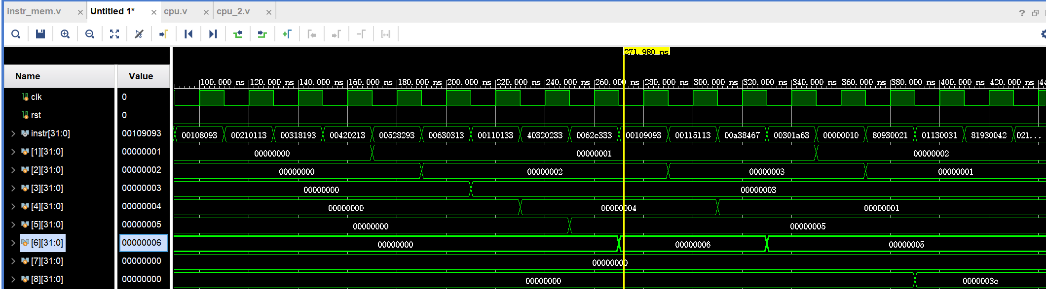
Figure 4. Simulation result graph (Photo/Picture credit: Original).
Where instr is the instruction, the simulation uses eight registers x1 to x8. Data hazard was deliberately avoided during the simulation, and no problems occurred when the instructions were parallel, which can verify that the structural hazard and control hazard of the pipeline have been solved.
5.2. Data hazard solution testing and analysis
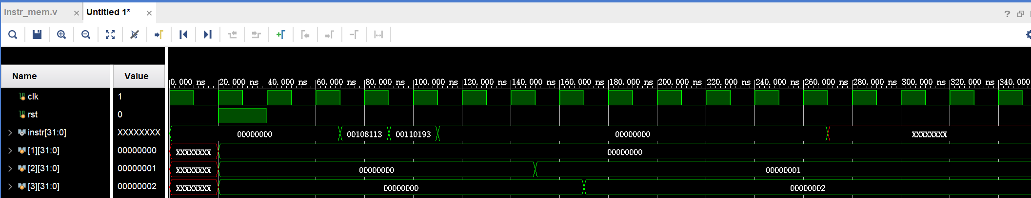
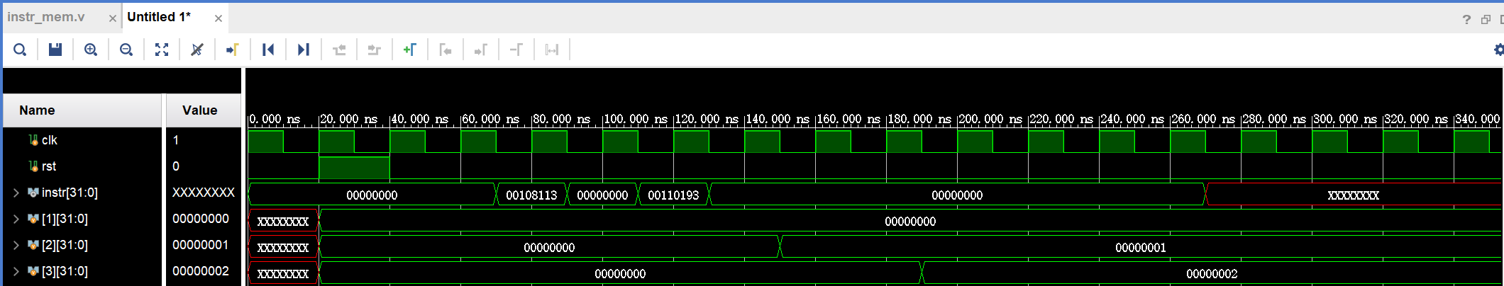
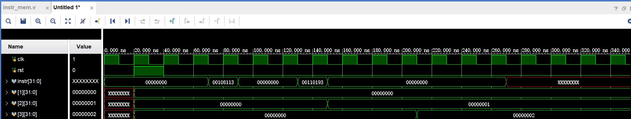
Instr means instruction, it can be deduced from figures that the two instructions are separated by one cycle, two cycles, and three cycles. When no additional registers are introduced, the value of X2 simply becomes 1 in the following three cases, which are caused by the three data hazards mentioned above. When additional registers are introduced, the simulation results show that the value of x3 successfully becomes 2, indicating the previous use of registers to solve the problem of data hazard. The results of solving the three types of data hazards are shown in Figure 5. The results of solving the first data hazard are shown in Figure (a), the results of solving the second data hazard are shown in Figure (b), and the results of solving the third data hazard are shown in Figure (c).
(a)
(b)
(c)
Figure 5. Three kinds of data hazards after the simulation diagram (Photo/Picture credit: Original).
6. Conclusion
In order to realize the pipeline structure of RISC-V, it must solve the problem of structural hazard, and only in certain cases will there be control hazard and data hazard, control hazard will appear when the jump instruction and data hazard will appear when the source register and destination register of adjacent instructions overlap. By introducing four types of registers, the above three kinds of hazard problems are solved successfully and the five-level pipeline structure of RISC-V is realized. However, there are still some problems in the design. For example, there are still many kinds of data hazards, which have not been solved. Moreover, the method of introducing registers occupies a lot of resources and has a large hardware area, which is a relatively low-efficiency pipeline. In the future design to solve the hazard, can also be combined with branch prediction, hardware blocking, and other methods to solve the hazard.