


1. Introduction
The stepper motor can adjust the motor speed in a wide range simply by changing the pulse frequency, and it can start, brake, and reverse quickly. Its step angle and speed are not affected by voltage fluctuations and load changes, nor by environmental conditions. Therefore, these motors are very suitable for open-loop systems, making the whole structure simple and reliable, and they are often used in various digital control systems such as computer peripherals and machine tool program control [1]. The drive control system of stepper motor has a complex structure, various design types, and a wide range of applications. In this paper, the authors focus on designing and studying three different circuits for driving stepper motors, and by comparing the performance analysis of different types of chips used in the design, they speculate on the differences in the main performance indexes of stepper motors under their drive, and finally summarize the advantages and disadvantages of the three circuits in a reasonable analysis to arrive at the optimal circuit [2, 3]. It gives designers some inspiration to use specific chips to drive stepper motors to work, especially the design method of using a microcontroller with specific driver chips, which is easier to operate in reality and can drive stepper motors with different voltage ratings by changing the program entered in the microcontroller [4, 5].
2. Stepper motor drive circuit design
The normal operation of the stepper motor requires a special driver, which is a control amplifier that energizes each winding of the motor in turn. At present, mainly by using a special chip or microcontroller to complete the control and drive of the stepper motor, the following will introduce three stepper motor drive circuits, the first two of which are only driven by the special chip, the third is driven by the microcontroller and special chip together [6, 7].
2.1. Stepper motor driving circuit based on L297 and NE555
2.1.1. System diagram of the driver circuit. The control signal voltage of this circuit is DC 5V, and the power supply voltage of the stepper motor is DC 12V, which can realize the control of the rotation and steering of the stepper motor. The whole system of stepper motor driving circuits is divided into the following five parts.
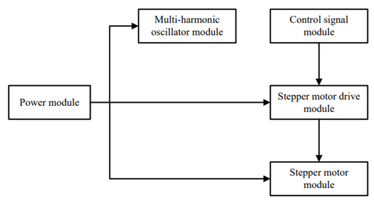
Figure 1. Drive circuit system using L297 and NE555
The stepper motor drive module here is driven using the L297 chip, which receives stepper clock, direction, and mode signals from the control signal module and generates control signals for the power stage. The L297 generates four-phase drive signals for two-phase bipolar and four-phase unipolar stepper motors in stepper motor control applications, and the PWM chopper circuitry in the chip allows switching-control of the current in the windings.
The multi-harmonic oscillator module consists of the NE555, a highly stable controller that generates precise delays or oscillations. Here it operates steadily as an oscillator, while its free-running frequency and duty cycle are precisely controlled by two external resistors and a capacitor [8-10].
2.1.2. Schematic diagram of the driving circuit. As shown in Figure 2, the switch control module is on the upper right, where SW1 is connected to pin 10 of L297 to control the stopping of the motor; SW2 is connected to pin 19 of L297 to control the rotation of the motor; and SW3 is connected to pin 17 of L297 to control the steering of the motor [8, 9].
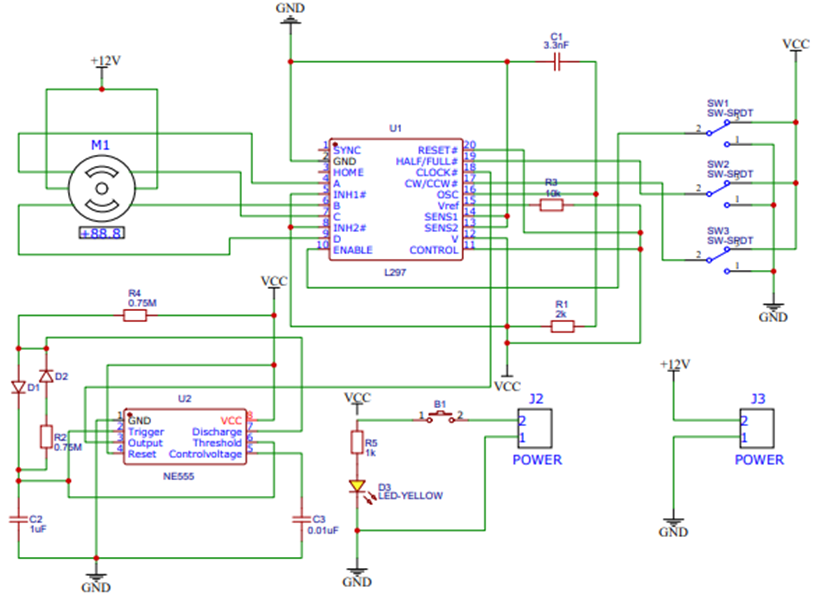
Figure 2. Schematic of the driver circuit based on L297 and NE555
The lower left is a multi-harmonic oscillator module consisting of a NE555 that generates the clock signal input to the L297 chip, which is a square wave signal with a frequency of 1Hz, output from pin 3 of the NE555 to the CLOCK input on pin 18 of the L297. The control signal module can be analogous to the switch control module, which is connected to the L297 chip of the driver module to control the stopping, turning, and steering of the stepper motor [10].
The core drive module, i.e., the L297 chip, outputs 4-phase drive signals A, B, C and D on pins 4, 6, 7 and 9. Pin 10 is an enable input, when it is low, A, B, C and D are also low and the stepper motor does not work. Pin 11 is the chopper control terminal, when it is at a high level, it has inhibit effect on A, B, C and D; and when it is low, it has inhibit effect on the inhibit terminals INH1 and INH2, thus controlling the motor and torque. Pin 17 is the steering control terminal, when the level of this pin changes, the stepper motor steering also changes. Pin 19 is the working mode control terminal, when it is high, it is half-step working mode; when it is low, it is full-step working mode [8, 9].
This circuit drive module is completed by only one L297 chip. Although the structure is simple and easy to build, the control content is small. It can only control its rotation and steering, and it needs to constantly change the level state of several pins to achieve the control requirements, which is not easy to operate. In addition, the working voltage of the stepper motor it can drive is small, and in many cases, such stepper motors cannot drive the load.
2.2. Stepper motor driving circuit based on L297 and L298
2.2.1. System diagram of the drive circuit. The control voltage signal of this circuit is DC 5V, and the power supply voltage of the stepper motor is DC 3-46V, with forward and reverse switch control, which can realize forward, reverse, and stop of the stepper motor, and the whole circuit system is divided into four parts.
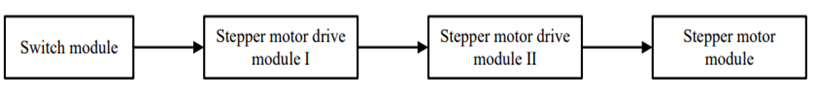
Figure 3. Drive circuit system using L297 and L298
The L297 chip acts as a stepping pulse timing divider in the sub-circuit and can drive the L298 so that the stepper motor can work properly with only two control signals: stepping pulse and forward/reverse rotation.
L298 is a dual full-bridge stepper motor driver chip, containing two H-bridge high-voltage, high-current dual full-bridge drivers, receiving standard TTL logic quasi-position signal, which can drive a higher operating voltage stepper motor, and able to adjust the output voltage directly through the power supply. It has two enable controls, and the two enable controls of L298 are connected high, so that the stepper motor cannot be speed regulated [8, 9, 11].
2.2.2. Schematic diagram of the drive circuit. The use of L297 and L298 for driving stepper motors is very common and can form a complete PWM constant current chopper driver with a fixed chopping frequency for stepper motors. This circuit is suitable for driving two-phase bipolar stepper motors, and the specific principle wiring diagram is shown in Figure 4.
The four-phase output signal of L297 is directly connected to the four-phase input of L298, and INH1 and INH2 of L297 are two inhibited control signals connected to the two enable inputs of L298, which can be used to ensure the fast decay of load current when the winding is disconnected [9, 11].
When the switch SW4 is in high state, the stepper motor reverses. When SW4 is in a low state, the stepper motor turns forward. And pin 19 of L297 is at a high level, the stepper motor works in half-step mode, and pin 19 is at a low level, the stepper motor works in full-step mode.
On the far right is a dual Schottky diode bridge containing eight Schottky diodes, which are arranged as two separate diode bridges, especially for bipolar stepper motors, able to drain the reverse current generated when the motor is rapidly transformed in the operating state due to the low forward voltage drop and fast reverse recovery time [8].
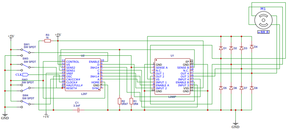
Figure 4. Schematic of the driver circuit based on L297 and L298
This circuit can be controlled by a switch and can realize the motor forward, reverse, and stop functions, but it still needs to change the level state of a few L297 pins to achieve the purpose of controlling the motor movement. By adding a driver module of L298, it is possible to drive a stepper motor with a larger operating voltage, and this driver circuit can be used in a wider range.
2.3. Stepper motor drive circuit based on ULN2003A and AT89C51 microcontroller
2.3.1. System diagram of the driver circuit. This circuit controls the stepper motor with an operating voltage of 12V through the AT89C51, which can realize the function of the stepper motor forward, reverse, and stop. The microcontroller is connected to two buttons for forward and reverse rotation to control the angle of forward and reverse rotation of the stepper motor. The circuit is divided into three main modules as follows.
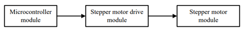
Figure 5. Drive circuit system using ULN2003A and AT89C51
The microcontroller module uses AT89C51, which is a low-power, high-performance CMOS 8-bit microcomputer. By writing the microcontroller program in advance, it sends out control signals to achieve a certain angle of stepper motor rotation in a specific direction with each key press.
The driver module consists of the ULN2003A chip, which contains seven independent Darlington tube driver circuits with an internal design of current-continuing diodes for driving inductive loads such as stepper motors. It can be directly connected to TTL/CMOS circuits at an operating voltage of 5V and can directly process data that previously required a standard logic buffer to process [8, 12, 13].
2.3.2. Schematic of the driver circuit. The most important microcontroller module, AT89C51 is connected to the reset circuit, clock circuit, AT89C51 reset requires 24 clock cycles of high level. The reset circuit allows the program to be executed from address 0. As shown in Figure 6, the reset circuit is a circuit connected to RST on pin 9 of the microcontroller. When a key is pressed, the RST pin level is high, and a high reset signal is input into the AT89C51 at this time. The clock circuit is connected to pins 18 and 19. A quartz crystal and two compensation capacitors are connected across XTAL1 and XTAL2 to form a crystal oscillator that helps the microcontroller's internal high-gain inverting amplifier form the clock signal [12].
Pins 1, 2, 3 and 4 of ULN2003A are channel input pins, which are connected to pins 21, 22, 23 and 24 of the output signal terminal of AT89C51 to receive the signal from the microcontroller; pins 13, 14, 15 and 16 of the driver chip are channel output pins, which are connected to the stepper motor to control its normal operation [13].
Through the internal programming of the microcontroller, every time the forward key is pressed, the stepper motor will turn forward by a fixed angle, and every time the reverse key is pressed, the stepper motor will turn backward by a fixed angle. When people long press the forward key or reverse key, the stepper motor continues to turn forward or reverse, and when people release the forward or reverse key, the stepper motor stops turning immediately [14, 15].
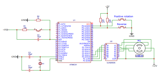
Figure 6. Schematic of the driver circuit based on ULN2003A and AT89C51
This circuit is controlled by a microcontroller, which generates more diverse control signals and can be programmed to achieve various control functions. It is easy to operate the stepper motor by simply pressing a switch. Although the stepper motor in this circuit is set to operate at 12V, this driver chip ULN2003A can drive a stepper motor with an operating voltage no higher than 40V, and the internal structure of this driver chip is simpler and easier to use than L297.
2.4. Summary
The first drive circuit is completed by a L297 chip. Although the structure is simple and easy to build, the control content is less, the operation is complicated, and it can only drive a smaller drive voltage stepper motor. The second drive circuit is controlled by a switch, which can realize the motor forward, reverse, and stop functions. By adding a drive module of L298, it can drive a stepper motor with a larger working voltage, and this drive circuit is more widely used. The third drive circuit is controlled by a microcontroller, which can be programmed to achieve more functions and is simple to operate. The motor can be controlled by pressing a switch, and the drive voltage can be set within the driving range of ULN2003A according to the rated voltage of the stepper motor to be driven [8].
3. Conclusion
In this paper, we have introduced three circuits for driving stepper motors, and we have chosen two major directions of mainstream specific chips and microcontroller drivers. The specific chip is selected by consulting the chip data sheet and a part of the reference materials to filter out several mainstream driver chips, and the microcontroller is selected from the common AT89C51, and the circuit design is drawn according to the pin functions of each chip provided in the data sheet. The three circuits have their own advantages, among which the driver circuit controlled by the microcontroller is simple and stable, it can control the motor in forward and reverse directions by pressing a button, and it can drive a stepping motor with a wide range of operating voltage. There are many types of special drive chips for stepper motors, and the model chosen in this paper is not necessarily the best choice, but only provides design ideas for the reader. Among the three types of circuits, the most used and most flexible is the microcontroller-controlled drive circuit. The author hopes readers can give priority to the microprocessor when designing the drive circuit.