

1.Overview of DTL Linear Accelerator
The Drift Tube Linac (DTL) is a common room-temperature linear accelerator structure, typically used immediately after the Radio Frequency Quadrupole (RFQ) to further accelerate the beam energy to hundreds of MeV/u. By using a series of drift tubes and acceleration gaps, DTL achieves step-by-step acceleration of charged particles and is a key component in medium-high energy accelerator systems.
The earliest widely used drift tube accelerator structure is the Alvarez type. The Alvarez-type DTL is suitable for accelerating particles with an energy range of 0.75–150 MeV/u (β=0.04 – 0.5), with a working frequency generally below 200 MHz and an effective shunt impedance less than 40 MΩ/m [1]. Its characteristic feature is the placement of focusing magnets inside each drift tube to provide transverse focusing. However, this design results in larger drift tube sizes, complex structures, and higher manufacturing and maintenance costs. Additionally, the presence of internal magnets limits the minimum size of the drift tubes, affecting the miniaturization and high-frequency development of the accelerator.
To address these problems, the H-type structure was proposed. The H-mode accelerating structure, also known as the Transverse Electric (TE) mode structure, is an accelerator structure dominated by RF magnetic fields. This structure no longer places the magnets inside the drift tube, so the size can be significantly reduced. Its RF electric field is mainly concentrated in the inner region of the cavity, with a more uniform electric field distribution. The distance between the centers of adjacent acceleration gaps along the longitudinal direction is βλ/2, with a phase shift of π. This design makes the structure more compact, which is conducive to improving acceleration efficiency and reducing costs.
1.1.Two Types of H-Structure
The H-structure primarily consists of two types: the IH structure [2] and the CH structure [3].
1.1.1.IH-DTL (Inter-digital H-mode Drift Tube Linac)
The IH-DTL structure was first proposed by J.P. Blewett at a CERN symposium in 1956 [9] and has since been applied in several projects. The IH structure employs inter-digital electrodes, with coupling between drift tubes achieved through the cavity wall. This design results in a more ideal electric field distribution in the acceleration gaps, thereby enhancing the acceleration gradient. IH-DTLs typically operate at frequencies below 300 MHz and possess effective shunt impedances of 100–300 MΩ/m or even higher. Generally, the IH structure is more effective for accelerating particles with a velocity β below approximately 0.1. However, its asymmetry may introduce a dipole component in the electric field, causing beam centroid offset during transmission. This effect can be mitigated by optimizing the shape of the drift tubes.
The IH structure is characterized by high shunt impedance and acceleration efficiency, making it particularly suitable for the acceleration of heavy ions in the low- to medium-energy range. Due to these advantages, the IH structure has been widely applied in the production of medical isotopes, neutron sources, and proton and heavy-ion therapy devices.
1.1.2.CH-DTL (Cross-bar H-mode Drift Tube Linac)
The CH-DTL is an improvement based on the IH structure. It typically operates in the TE₂₁₀ mode and is more effective for accelerating particles with a velocity β ranging from approximately 0.1 to 0.5. It is also suitable for higher frequencies (150 MHz–1 GHz).
The high shunt impedance and transit time factor (TTF) of the CH structure give it an advantage in high-power applications. As a result, it has been widely used in the medium- to high-energy acceleration sections of proton and ion linear accelerators, especially in the field of superconducting RF technology. In CH-DTL cavities, drift tubes are supported in a cross-bar arrangement, which provides high stability and good symmetry. The power dissipation in the cavity is also uniformly distributed. Compared to the IH structure, the CH-DTL is easier to cool with water, making it highly potential for continuous wave (CW) operation.
1.2.Comprehensive Advantages of H-Structure
The high shunt impedance of these H-mode structures is mainly attributed to the compact drift tube design, which reduces the size of the drift tubes and the capacitance. Additionally, the use of π-mode operation enhances the transit time factor, synchronizing the accelerating electric field with the particles and improving the acceleration effect. The H-structure can be directly connected to an RFQ accelerator without the need for a transition section, simplifying the overall design of the accelerator. For transverse focusing of the beam, the H-structure typically employs a combination of quadrupole-triplets or magnetic solenoids. These focusing elements provide sufficient focusing power while maintaining a compact structure.
In terms of mechanical strength, the IH and CH structures, with their more compact and symmetrical designs, have higher mechanical strength than Alvarez cavities. They possess better structural stability and resistance to deformation, which is crucial for maintaining the long-term stable operation of the accelerator.
The H-structure is widely applicable in both light-ion and heavy-ion acceleration fields, meeting the acceleration needs of various ions. They can be used in both room-temperature accelerators and in combination with superconducting technology to further enhance the acceleration gradient and efficiency. With the development of high-power RF technology, the H-structure demonstrates excellent performance under high electric field strength and high duty cycle conditions, making it suitable for high-intensity accelerators and neutron sources.
In terms of technological development, advanced computer simulation tools have been used to precisely analyze the electromagnetic field distribution, thermal characteristics, and mechanical stress of the H-structure, optimizing its design. Precision machining and the application of new materials have improved the manufacturing accuracy and performance of accelerator components. Additionally, the introduction of superconducting materials in the CH structure has reduced RF losses and enhanced the overall efficiency of the accelerator.
In summary, drift tube linear accelerators, especially the IH and CH types of H-structure, have become an important component of modern linear accelerator technology. They play a key role in improving acceleration efficiency, reducing costs, and meeting diverse scientific and industrial application needs.
2.DTL Principle
The beam dynamics design of H-type Drift Tube Linac (DTL) typically employs the Alternating Phase Focusing (APF) method and the KONUS dynamics principle. The APF method was first proposed by M.L. Good in 1953 [4]. It eliminates the need for traditional transverse focusing elements such as solenoids or quadrupole magnets, relying solely on alternating positive and negative synchronous phases to achieve transverse and longitudinal focusing of the beam. Its main advantages include simple RF design, compact cavity structure, and low cost. Combining the APF dynamics principle with the IH structure results in high shunt impedance and a simple structure that is easy to manufacture. This combination has been widely applied in low-energy linear injectors, such as the 4 MeV/u linear injector of the carbon-ion cancer therapy facility at Japan’s HIMAC [5], the heavy-ion cancer therapy linear injector at the Institute of Modern Physics in Lanzhou [5], and the muon linear accelerator at Japan’s J-PARC [6]. However, the APF method also has some limitations, including low acceleration gradient, significant emittance growth, and poor longitudinal phase space quality. The KONUS (Kombinierte Null Grad Struktur, or Combined Zero-Degree Structure) dynamics principle is another important beam dynamics design method for H-type DTLs, proposed by U. Ratzinger et al. in the 1990s [7][8]. This method is for achieving efficient acceleration and focusing in H-type DTLs. By combining magnets with nagtive phase drifts to longitudinal focusing and the zero phase accelerating drifts, it enables efficient acceleration and focusing control of the beam. Its main features include high acceleration efficiency, effective focusing control, and flexible design. The length ratio of acceleration sections to focusing sections can be adjusted according to requirements to optimize beam dynamics performance. The KONUS principle is widely used in high-power and high-energy ion accelerators, especially in designs that require high acceleration gradients and high-quality beams.The KONUS has the following design features:
Zero Synchronous Phase Acceleration Sections: In these sections, the synchronous phase is set to 0°, allowing particles to gain maximum acceleration voltage at the peak of the electric field, thereby achieving a high acceleration gradient.
Focusing Sections: Drift sections are inserted between acceleration sections, and external focusing elements such as quadrupole lenses or solenoids are arranged within these drift sections to achieve transverse focusing of the beam.
Negative-phase longitudinal bunching sections: In these sections, the synchronous phase is set to lower than 0°, allowing particles to be bunching longitudinally.
This design offers several advantages:
1.High Acceleration Efficiency: Particles achieve maximum energy gain under zero synchronous phase, resulting in high overall acceleration efficiency.
2.Good Beam Quality: By introducing focusing elements in the drift sections, the growth of beam emittance can be effectively controlled, maintaining good beam quality.
3.Design Flexibility: The length, number of acceleration and focusing sections, and parameters of focusing elements can be flexibly adjusted according to specific requirements, adapting to various acceleration needs.
The KONUS principle has been applied in a variety of accelerators, especially in high-power, high-current ion accelerators. For example: GSI (Gesellschaft für Schwerionenforschung, German Heavy-Ion Research Center): H-type accelerators using the KONUS principle have achieved efficient heavy-ion acceleration. FAIR (Facility for Antiproton and Ion Research) Project: The KONUS dynamics design has improved accelerator performance and beam quality, providing an advanced platform for nuclear physics and heavy-ion research.
Compared to the APF method, the KONUS method uses zero synchronous phase, resulting in greater energy gain for particles in the acceleration sections and higher acceleration efficiency than the APF method. The KONUS method achieves transverse focusing through external focusing elements, which can more effectively control the growth of beam emittance, whereas the APF method typically experiences significant emittance growth and relatively poorer beam quality. The APF method does not require additional focusing elements and has a simpler structure, while the KONUS method requires integrating focusing elements into the cavity, increasing the complexity of design and manufacturing.
3.International DTL Projects
CERN (European Organization for Nuclear Research):
In CERN’s proton accelerator chain, DTL structures are used in linear accelerators such as Linac2 and Linac4 to accelerate protons from low-energy stages (MeV level) to medium energies, providing suitable injection energies for subsequent synchrotrons, such as the PS Booster [10].
KEK (High Energy Accelerator Research Organization) and J-PARC (Japan Proton Accelerator Research Complex):
In Japan’s J-PARC facility, the Linac section employs DTL and SDTL (Separated DTL) as accelerating structures, accelerating proton beams from 3 MeV to 50 MeV (DTL stage), followed by further acceleration to around 181 MeV by the SDTL [11][12].
CSNS (China Spallation Neutron Source):
The Linac section of CSNS includes RFQ and DTL, accelerating proton beams from 3 MeV to 80 MeV to provide injection beams for the subsequent Rapid Cycling Synchrotron (RCS) [13][14].
3.1.Development Prospects of DTL Accelerators
With the advancement of RF technology, increasing the operating frequency of accelerators can reduce their size and enhance the acceleration gradient. The application of H-type structures at higher frequencies is gaining increasing attention. Additionally, the use of superconducting materials in DTLs can reduce RF losses, improve acceleration efficiency and gradient, and represents an important direction for future accelerator technology. Superconducting CH structures have already been validated in several projects. DTL accelerators play a significant role not only in high-energy physics research but also have broad application prospects in fields such as materials science, medicine (e.g., radiotherapy and isotope production), energy, and the environment.
However, several challenges remain: With high-power operation, the increase in thermal load necessitates effective cooling systems and thermal management solutions to ensure stable accelerator operation. High-precision beam control requires good mechanical stability of the accelerator structure. Advanced manufacturing processes and material selection can enhance the structure’s resistance to vibration and deformation. Developing high-efficiency, high-reliability RF power sources, such as solid-state RF amplifiers, can help reduce operating costs and improve system reliability.
4.Dynamic Design of DTL
This paper needs to carry out a preliminary DTL dynamic design based on the distribution of Sn22+ particles at the RFQ outlet, which requires that the particle output energy is not less than 0.95MeV/u, the transmission efficiency is 100%, and the emittance growth is less than 25%.
The design of the DTL primarily utilizes LORASR. LORASR is a tool for longitudinal dynamic simulation and optimization of linear accelerators (especially DTL). It can efficiently track the evolution of particles in phase space, optimize the geometric design of drift tubes and the distribution of acceleration gaps, and supports the efficient design of KONUS mode. By combining RF parameters with dynamic simulations, LORASR provides precise methods for improving acceleration efficiency and optimizing structure, suitable for the design and research of both room-temperature and superconducting linear accelerators [15][16].
This low-frequency heavy-ion DTL is expected to accelerate particles from 500 keV/u at the DTL exit to 950 MeV/u. The beam matching between the RFQ and DTL is achieved through a Medium Energy Beam Transport line (MEBT) for transverse and longitudinal matching.
Table 1: Main parameters of LORASR dynamic design.
|
Gap |
TTF(Axis) |
Acceleration gradient on axis (MV/cm) |
Effective voltage(MV) |
Phase of center particles /deg |
|
1 |
0.778 |
0.03673 |
0.11000 |
1.40635 |
|
2 |
0.794 |
0.03943 |
0.12035 |
-1.0998 |
|
3 |
0.794 |
0.04186 |
0.13035 |
-3.52585 |
|
4 |
0.810 |
0.04679 |
0.14025 |
-5.8555 |
|
5 |
0.811 |
0.04582 |
0.14024 |
-8.074 |
|
6 |
0.811 |
0.03857 |
0.12030 |
-10.1677 |
|
7 |
0.796 |
0.03479 |
0.11000 |
-12.09595 |
|
8 |
0.719 |
0.04549 |
0.15000 |
0.0472 |
|
9 |
0.765 |
0.05221 |
0.18000 |
0.14985 |
|
10 |
0.766 |
0.05133 |
0.18000 |
0.3581 |
|
11 |
0.756 |
0.05266 |
0.19000 |
0.55865 |
|
12 |
0.754 |
0.04164 |
0.15000 |
4.4628 |
|
13 |
0.768 |
0.04900 |
0.18000 |
2.69215 |
|
14 |
0.767 |
0.04807 |
0.18000 |
0.8844 |
|
15 |
0.767 |
0.04980 |
0.19000 |
-0.88725 |
|
16 |
0.767 |
0.05142 |
0.20000 |
-2.73725 |
|
17 |
0.767 |
0.05046 |
0.20000 |
-4.5931 |
|
18 |
0.767 |
0.04956 |
0.20000 |
-6.48885 |
|
19 |
0.734 |
0.03697 |
0.15000 |
-8.3945 |
The dynamic structure mainly includes parameters such as the inner diameter and length of the drift tubes, gap voltage, and phase. After repeated adjustments, the final design consists of 2 KONUS periods, with 19 gaps and two sets of triple quadrupole lenses (QT), and a total length of less than 1.9 m. The peak voltage of each gap, TTF (Transit Time Factor), effective voltage, and phase of the central particle are summarized in Table 1.
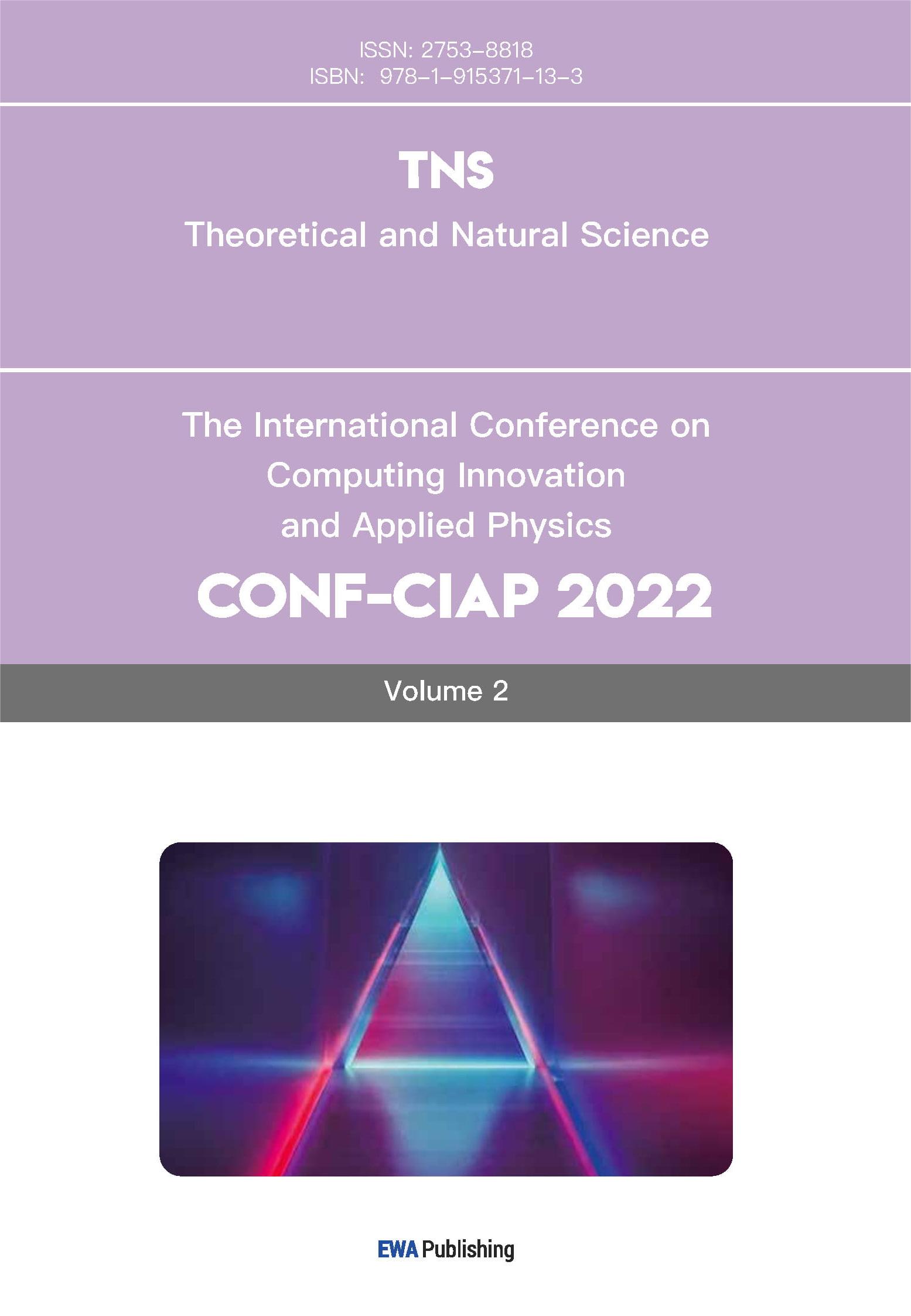
LORASR provides the TTF for the central axis and three transverse positions at different distances from the central axis of each gap (0.0D, 0.2D, 0.315D, and 0.4D). The variation of TTF with gap is shown in Figure 1. The effective time factor TTF1 on the central axis is the design standard, with a minimum of 0.719 in the tenth gap and a maximum of 0.811 in the first, seventh, and eighth gaps.
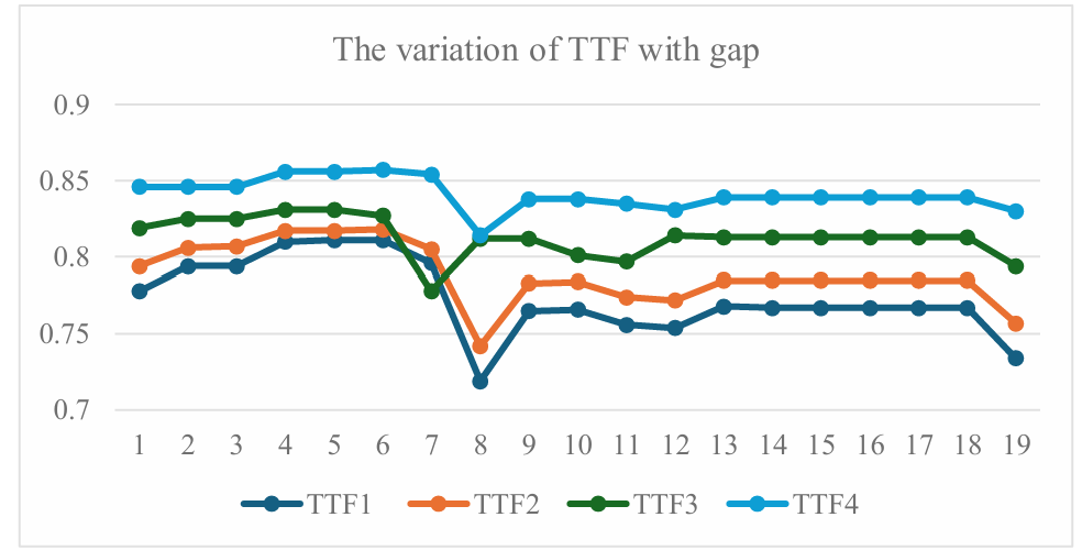
Figure 1: Variation of TTF with gap in the DTL.
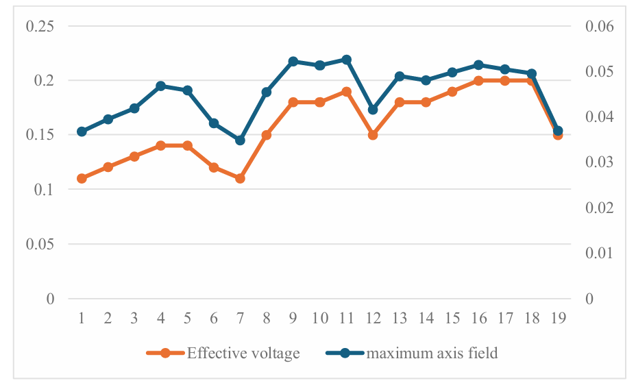
Figure 2: Variation of maximum axial electric field and effective voltage with gap in the DTL.
The distribution of the maximum electric field and effective voltage for each gap is shown in Figure 2. The energy growth of particles is shown in Figure 3. The entrance energy is 0.5 MeV/u, and the exit energy is 0.97 MeV/u, meeting the energy design requirements. The positions in the figure where the energy remains flat without growth are located within the QT. The design of the DTL for accelerating heavy ions also requires increasing the transverse and longitudinal acceptance and controlling the growth of beam emittance in both directions. This paper adopts the method of increasing the aperture of the entrance drift tube to enhance the transverse acceptance, thereby improving the transmission efficiency of heavy ions. The final inner radius of the drift tube is 15 mm. Figure 4 shows the variation of the particle envelope in the x and y directions. The maximum transverse envelope radius of the beam transmission is within the magnet, and the maximum envelope in the drift tube does not exceed 10.0 mm. Therefore, the designed apertures have sufficient margin to effectively avoid space charge effects caused by halo particles. The entrance energy spread and phase width of Sn²²⁺ and multi-charge-state mixed particles are within the acceptance range of the DTL, so the beam can be captured and accelerated. Figure 5 shows the length distribution of each gap, and as can be seen that the gap gradually increases as the beam energy increases.
Figure 3: Energy growth of synchronous particles in the DTL.
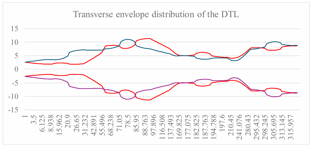
Figure 4: Transverse envelope distribution in the DTL.
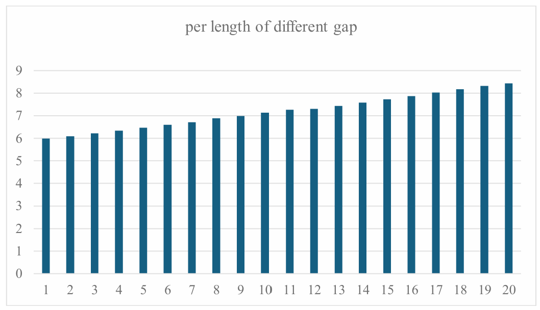
Figure 5: Lengths of each gap.
5.Conclusion
This paper focuses on the principles, structures, and designs of Drift Tube Linacs (DTLs), introducing the characteristics and developments of the traditional Alvarez structure and the modern H-type structures (IH and CH types). The H-type structure, with its high acceleration efficiency and compactness, performs excellently in the low- to medium-energy range, especially in heavy-ion acceleration and medical applications, where it has broad prospects for application. The paper analyzes the high shunt impedance of the IH structure and its advantages for accelerating low-velocity particles, while also exploring the significance of the mechanical and thermal stability of the CH structure for high-frequency acceleration, highlighting the potential of H-type structures in the combination of room-temperature and superconducting technologies.
In terms of dynamic design, this paper elaborates on two principles: APF and KONUS. The APF method achieves focusing through alternating phases and is suitable for simple, low-cost accelerator designs, but it has the issue of significant emittance growth. In contrast, the KONUS principle, which combines zero synchronous phase acceleration sections with focusing sections, achieves high acceleration efficiency and good beam quality, making it suitable for high-energy and high-power accelerators. The paper provides an in-depth exploration of the advantages of the KONUS principle and points out its flexibility and potential for design optimization in practical applications.
In the dynamics design, this paper utilizes the LORASR software to complete an 81.25 MHz DTL design based on the KONUS principle. The design includes 19 acceleration gaps and 2 KONUS periods, with a total length of less than 1.9 meters. By optimizing the geometric parameters of the drift tubes, the voltage and phase of the acceleration gaps, the design achieves 100% transmission efficiency and controls emittance growth to below 25%, while ensuring loss-free particle transmission. The design particularly optimizes the drift tube aperture to enhance transverse acceptance, with the maximum envelope radius controlled to less than 70% of the drift tube inner diameter, avoiding the impact of space charge effects and ensuring the stability of high-quality beams. The reliability of the design is demonstrated through visualized results of TTF distribution and energy growth.
In conclusion, Drift Tube Linacs, especially the IH and CH designs of H-type structures, with their high acceleration efficiency and flexible design advantages, meet the needs of scientific research and industrial applications while advancing accelerator technology. In the future, with the development of RF technology and superconducting materials, DTL technology will further enhance performance, providing more efficient and reliable solutions for high-energy physics, medicine, materials science, and other fields.