


1. Introduction
In today's world, we need to gather and process a large amount of data to support scientific and technological progress. For measuring instruments, we hope to obtain real-time measurement data instead of relying on manual meter readings to obtain discrete data while minimizing labor costs, so we need to be able to convert the dial readings designed by the pointer into numbers that can be input into the computer. However, for many countries where smart meters are not popular, replacing traditional water meters with smart water meters will be a huge expense [1]. In this case, the use of computer vision-based meter detection technology can save the cost of a large number of water meter iterations and have better cost performance.
Existing research is worth reviewing, as some studies have identified how to determine meter readings. A computer system for recognizing meter readings was designed and implemented using two parts for data analysis. The first part includes recognizing needle rotation, scale arc, and scale limits, which were located to achieve the actual calibration of the second part. This algorithm uses background subtraction and the Hough transform for the localization of lines [2].
At the same time, using a similar concept, the methods can also be applied through edge detection and Hough transformation, and the required value can be determined by comparing the angle of the pointer and the maximum deflection [3].
After that, in order to solve the parallax error, an all-digital solution based on the Hough transform was developed, along with a statistical processing method for reading out high-precision analog instruments for pointer indicators [4].
In instrument reading, both accuracy and universality are very important. We hope to test some common computer-vision-based instrument testing methods, and try to let them read as many cases as possible, then analyze and modify the program according to their output results.
2. Background
Nowadays, electronic measuring instruments are a mature technology that has played a huge role in all fields of society, including engineering areas or common domestic households. According to statistics, the global penetration rate of smart meters will reach 53% by 2025. In this process, price and cost are factors that cannot be ignored [5].
According to the prices provided by three Internet companies in China, taking 200 users as an example, the average price of replacing traditional water meters with intelligent electronic water meters is 37,213 yuan, which will be a huge number for a wider use scenario [6].
In this case, the method of adding measuring cameras to traditional instruments seems to be more cost-effective. First, the price of simple cameras is much cheaper than that of replacing intelligent water meters and their management and control platforms. Second, nowadays, digital communications and digital instruments for automatic monitoring processes are well-developed technologies [7].
At present, the method used by most researchers is to obtain the image data of the instrument, convert the data into the corresponding text form, and finally achieve the purpose of reading, collecting, and gathering analysis of the reading information. The core of this method lies in the construction of an image recognition algorithm. The difficulty lies in the real-time reading, accuracy, and adaptability to the environment. We found three ways we can use computer vision to solve this problem.
The first program determines the pointer by judging the distance between the detected line and the center of the circle and uses the value entered by the user to determine the scale and final reading. Both the second and third programs determine the position of the pointer by judging the length of the detected straight line. The difference is that the second program improves accuracy by removing the dial, while the third program is more appropriate for multimeter readings.
3. Methodology
3.1. Bisect dial method
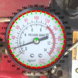
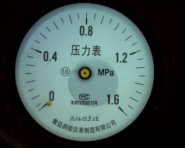
First, grayscale processing is performed on the image, in order to simplify the matrix and improve the operation's efficiency. Detect possible circles with different diameters in the image, and then average the diameters to find the desired circle to the greatest extent. Then mark the center of the circle on the basis of the detected circle, and draw a scale line in units of 10° as a benchmark for subsequent determinations of readings.
This system hopes to determine the minimum and maximum offset positions of the pointer of the meter and the corresponding scale readings through the user's manual input of the meter's basic information. So it is necessary to allow users to perform simple measurements and input parameters.
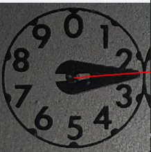
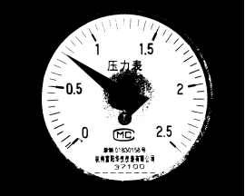
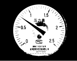
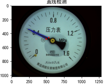
When performing pointer detection, it was found that the preprocessing of the image was not perfect. At the beginning, canning and blurring were performed on the picture, but the practice proved that they were not as good as the direct grayscale processing. In this way, the position of the pointer can be smoothly determined. Then, to associate the position of the pointer with the pointed angle, find the far end point of the pointer to determine its angle. In this case, calculating the angle of the pointer requires only calculating the arctan value corresponding to the end point. Then make some adjustments and correspondences according to the characteristics of the dial, and finally determine the angle and reading of the pointer.
|
Figure 1. Meter scales and pointers determined by the program. |
3.2. Remove the dial method
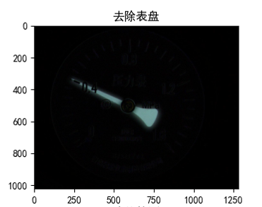
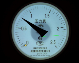
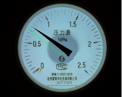
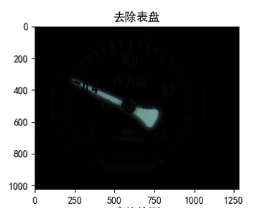
First of all, in order to facilitate subsequent processing, the image needs to be preprocessed. The image preprocessing link includes Gaussian denoising, image grayscale and binarization, and canny edge detection and obtains an image in which the dial is removed and only the pointer is retained.
|
Figure 2. The dial is removed by this procedure and the position of the hands is determined. |

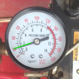
Since Hough line detection detects all possible straight lines in the picture, the operation of removing the dial is performed on the original picture. In the case of only pointers, find the longest two straight lines, and the angle between them is the endpoint of the pointer.
At the same time, the center of the circle and its corresponding radius can be found through the Hough circle detection, and the intersection of the aforementioned straight lines and the connection of the center of the circle can provide the minimum angle of the meter and the reading of the meter.
We have obtained the pointer line and the zero scale line above. By calculating the arctan value of the angle between the two lines, the angle can be calculated, and then the final dial reading can be obtained through the relationship between the angle and the dial.
3.3. Multi-table reading method
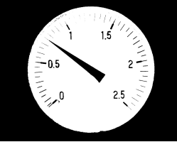
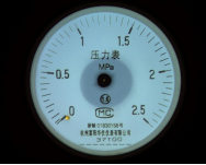
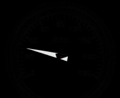
This method is similar to the second method, but is more suited to detect multiple meters. First, perform regular image initialization, including image graying, blurring, and canny. In order to make the small instrument in the picture have a better field of vision and detection, the method adjusts the intercepted ROI area to make the picture more clearly visible. In order to read multiple meters at the same time, a cycle is added to the method, which is used for judging, processing, and arranging the detected meters.
|
Figure 3. Continuous circle detection and determination of pointers. |
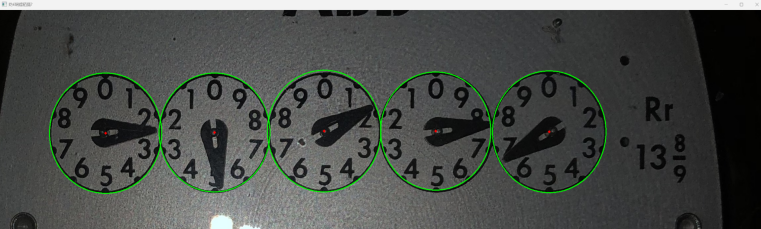
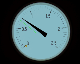
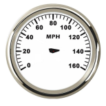
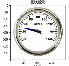
The method of detecting the position and angle of the pointer in this method is similar to the previous method. Detect the line, and then obtain the two sides of the pointer and convert them into rays to obtain their intersection points. The readings of the multiple gauges are then determined by the angles and characteristics of the panel and then arranged.
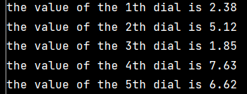
Figure 4. Continuous output of results.
4. Results and discussion
4.1. Bisect dial method
The program can accurately identify some gauges and readings. At the same time, it also has a certain ability to recognize some fuzzy dials, such as:
|
Figure 5. Successful running cases. |
However, when the pointer color resolution is not high and the background color is complex, it is likely to misjudge the pointer (green represents the position of the detected pointer). Although the program correctly recognizes the circle where the dial is located, the judgment of the pointer is not clear. When the parameters in the pointer function are judged to be correct, some changes are made to the dial and the pointer, so as to solve this problem. Binarize the initial dial to get the following image:
|
Figure 6. Error detection after binarization. |
Obviously, the pressure for straight line detection in the image is very high. Due to this program, when setting the length threshold for line detection, the range cannot be direct and accurate, which makes it almost impossible for the program to find the information of the instrument it wants to recognize. After analysis and experimentation, it is found that the difficulty of line detection may be related to the background of the picture, so a correction is made; all redundant backgrounds are removed:
|
Figure 7. Detection results after removing the background. |
It can be seen that the detection of the straight line is as close as possible to the pointer when there is an error in the dial information, which shows that the simplification of the background has played a huge role in the fineness of the image recognition. Sometimes there are errors because the program looks for the line closest to the center of the circle as the edge of the pointer, and the basic information is manually entered.
We chose to modify the pointer, hoping to find the relationship between the accuracy of straight line detection and the shape of the pointer. Although the recognition and discrimination of the dial and hands are not artificially reduced, due to the more regular shape, the pointer and the background are indeed more clearly distinguished during edge detection, and the position and length of the pointer detection can be further refined. optimization, so the location of the pointer is clearly visible:
|
Figure 8. The result after modifying the pointer shape. |
Although using some artificial methods can improve the recognition accuracy of some pictures, it is difficult for users to process a large number of pictures in a short time, or find a better measurement range and accuracy. At the same time, there are certain problems in the program itself, namely, that the pointer should pass through the center of the meter, but in many cases, the pointer detection is not satisfactory due to the influence of the shape and size of the pointer. This also reflects to a certain extent that dial reading programs have certain limitations, that is, the scope of application is small, and it is difficult to accurately identify other pictures.
4.2. Remove the dial method
The basic process of this program is similar to the above program, but the removal of the background is added to the program. The program puts two photos together and selects the brightest part to realize the separation of the pointer and the dial. The effect is shown in the figure below:
|
Figure 9. Separate instrument dials. |
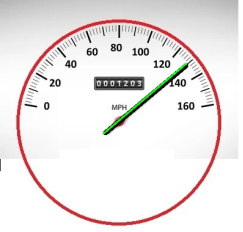
After removing the dial, the pointer is more precise and clear. At the same time, when running other instruments, it also has a more prominent performance:
|
Figure 10. The effect of different gauges after removing the dial. |
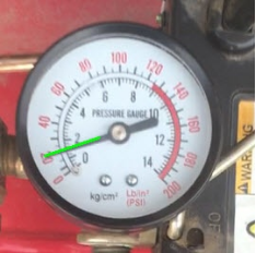
Since the logic of this program is to find the longest two sides in the picture as the two sides of the pointer, the threshold for the length of the pointer is not strict. In many cases, setting it to the minimum can also better find the desired variable. , mainly relying on the removal of the background greatly facilitates the reading of the pointer by the program:
|
Figure 11. Precise identification results of the program. |
This program has achieved good results in terms of modularity and ease of use. Compared with the second program, the reading accuracy has also greatly increased.
5. Conclusion
After a series of data collection and research, there are many ways to use computer vision to read meters, but the general ideas are similar. Methods including removing the background noise of the instrument and enhancing the recognition of the pointer are all preparations for the program to better recognize the readings.
These simple and easy methods all have a serious drawback, which is that they solidify various information on the dial, making it difficult to read some different instruments. All in all, they lack adaptability and versatility. First of all, a lot of manual preparation is required before identification, which will consume a lot of resources and experience. The solidification of instrument information will make identification more difficult, and it is even difficult to identify some similar instruments.
In contrast, it is very difficult to let the computer automatically analyze the information from these meters and do the automatic analysis, and many current studies have also confirmed this point. The application of various machine learning technologies in computer vision is actually to make the computer's ability to recognize information more versatile and accurate, and to better meet the needs of engineering or life.