

1. Introduction
Watt's improved steam engine opened a new era of the industrial revolution, but the steam often condensed in the cylinder and increased low-heat losses, resulting in inefficient steam engines and safety hazards. In order to solve these problems, people began to think about using hot gas or hot air, which is less likely to condense, as a substitute to improve the machine's efficiency [1]. As a result, from the late 18th century to the early 19th century, various engines that used hot gases as work gases, including mixed and heated air, emerged recently. The Stirling engine, a hot gas engine, was invented by a Scotsman, Robert Stirling, in 1816. In recent decades, the Stirling engine has attracted much attention due to the increasing prominence of energy and environmental issues and the increasing level of technology [2]. One of the advantages of the Stirling engine is its suitability for many different energy types, including liquid, gaseous and solid fuels. It can generate electricity from virtually any high-temperature heat source through indirect heating using a heat-carrying system such as heat pipes. In addition, compared to other engines, the Stirling engine runs with very little noise because the combustion of the fuel is continuous, avoiding the bursting and intermittent combustion processes similar to internal combustion engines. Also, air pressure does not affect it because the work mass is isolated from the atmosphere in the Stirling closed loop, making it ideal for use at high altitudes. Starting from the 1980s, the Dutch company Philips started the research and development of the modern Stirling engine, which made the Stirling engine new and attracted the attention and interest of countries worldwide [3].
At present, many countries, including China, the United States, the United Kingdom, Japan, Germany, France and Canada, are actively developing Stirling engines to meet different needs, including Stirling engines for vehicles, coal-fired stationary Stirling power stations, solar Stirling power stations, fully implanted Stirling engines artificial heart power sources, Stirling engines for underwater use and agricultural Stirling engines [4]. Successful examples include the civilian 25KW external combustion engine from STM in the U.S. and the Stirling engine used in the Japanese pro-tide class submarines [5].
2. Working principle of Stirling engine
The Stirling engine is a thermo-mechanical device based on a gas cycle that converts thermal energy into mechanical energy. It mainly comprises a hot end, cold end, piston, cylinder and connecting rod. The working process of the Stirling engine is as follows: first, the gas (usually hydrogen, helium or air) is placed in the cylinder, and the hot end and cold end are heated and cooled separately [6]. When the hot end is heated, the gas is heated and expanded, generating a certain pressure to push the piston to the cold end; when the cold end is cooled, the gas is cooled and compressed, generating a certain negative pressure to attract the piston to move to the hot end. The piston drives the runner, generator, and other mechanical equipment through the connecting rod, thus converting heat energy into mechanical energy (Figure 1) [7].
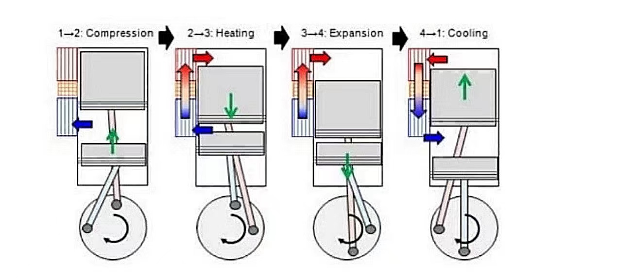
Figure 1. Working principle of the Stirling engine [8].
3. Application scenarios for Stirling engines
3.1. Power generation
Stirling engines can generate heat energy by burning wood, natural gas, and other fuels to drive a generator to generate electricity. Because of the high efficiency of the Stirling engine, its power generation efficiency is also relatively high [9].
3.2. Solar energy
Stirling engines can use solar energy to generate electricity. Solar energy is converted into thermal energy, and then the Stirling engine converts the thermal energy into mechanical energy to generate electricity. The solar Stirling engine is a key component of the dish solar power generation system, and its performance directly affects the dish system's operational stability and photoelectric conversion efficiency [10].
The main components of a dish-type solar thermal power system are dish-type parabolic concentrating mirrors that can rotate on two axes and automatically track the sun's position, a Stirling engine with a solar collector, and a generator and its power transmission system. These components interact with each other and play an important role in the overall power generation system [11]. During operation, the dish-type parabolic concentrator in the system collects the sunlight energy. It reflects the collected solar energy to the focal point of the concentrator so that the collected heat is of high heat flow density and can drive the solar Stirling engine placed at the specific location of the concentrator, which drives the generator to generate electricity [12].
3.3. Heating and cooling system
Stirling engines can be used for heating and cooling systems, such as home heating, air conditioning, etc. By converting energy through the Stirling engine, energy can be efficiently used. Stirling engine principle is the expansion piston from the far stop and the compression piston from the near stop, respectively, at the same time to reach the near stop and far stop, during the working gas all through the accumulator into the compression cylinder, while in the accumulator at each point along the process isothermal distribution of previously absorbed heat, to achieve a level of cooling, and generate kinetic energy [13].
4. Primary technology and key components of the Stirling generator
The Stirling engine is equipped with various components that work together to enhance its efficiency and lifespan (Figure 2). The gap seal is a non-contact gas seal that uses the gas film between the piston and cylinder wall as the sealing surface and lubricant [14]. The gas spring, which consists of the distribution and power pistons floating on a static pressure gas spring, eliminates piston and cylinder wall friction and wear, thereby ensuring long engine life. The elastic bearing, also known as the plate spring, depends on the change in working medium pressure, the elastic force of the plate spring, and the load of the linear generator, to generate recovery force. The gas piston, on the other hand, reciprocates the distribution piston to promote the cold and hot ends of the cylinder [15]. To withstand continuous high-temperature impact, the heating head of the engine is made of special stainless steel and copper. The engine's thermal efficiency is improved through a heat regenerator, while the cooler is formed by axial convection of the inner copper fin and circumferential convection of the outer fin. The dynamic and magnetic linear generator is generally used as the straight-line generator, and the Stirling generator is equipped with a rapid power control function during operation [16,17].
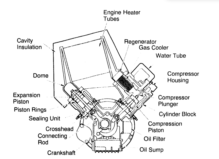
Figure 2. Key components of the Stirling generator [10].
5. Dynamic sealing performance of the Stirling generator
Different from the circulation process of internal combustion engine and gas turbine with suction and exhaust process (Figure 3), the Stirling engine cycle process is characterized by gas enclosed in an independent area, with no mass exchange with the outside world, and there is a very high-temperature difference or pressure difference between the upper and lower ends of the piston. The gas is easy to leak (Figure 4). Once the gas leaks, the engine will not run properly [17]. Therefore, the sealing performance of the engine is an important index to evaluate the quality of the Stirling generator [18].
5.1. Dynamic generator
The phase angle of the dynamic engine is realized by the mechanical device of the engine transmission system, and the torque generated by the engine drives a conventional asynchronous generator [19]. Dynamic generator generally adopts sliding seal [20].
5.2. Free-piston-type generator
Compared with the dynamic generator, the free piston generator has a simple structure, with only two moving parts, the gas distribution piston and the power piston. The two pistons are independent of each other and reciprocate in the same cylinder. The momentum generated by the engine drives the linear generator [21,22].
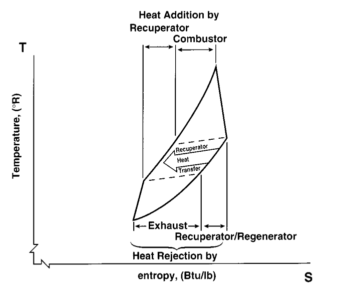
Figure 3. T-S diagram illustrating the heat transfer from the turbine exhaust to the compressor discharge accomplished by a recuperator/regenerator [23].
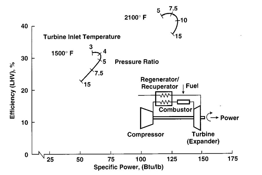
Figure 4. Performance map of a regenerative cycle gas turbine [23].
6. Conclusions
Compared with conventional engines such as diesel and gasoline, the Stirling engine has the following advantages for solar and residential use. The Stirling engine can use renewable energy sources such as solar energy, biomass, and geothermal energy as heat sources to convert thermal energy into mechanical energy. In contrast, conventional engines such as diesel and gasoline require fossil fuels, which produce large amounts of carbon dioxide and other harmful gases. It also showcases high efficiency and environmental protection. The Stirling engine's combustion process is sufficient to convert heat energy into mechanical energy and does not produce exhaust gas and pollutants. While conventional engines have problems such as exhaust emissions and noise. Stirling engine has a simple working principle, compact structure, and few parts, so it has high stability and reliability. Stirling engine is less noisy during operation, which will not affect the surrounding environment and human health. Stirling engine has fewer parts, so maintenance and upkeep costs are relatively low. Given this, Stirling engine has a broad application prospect in solar energy and residential use. For example, solar photovoltaic power generation systems can be combined with Stirling engines to build solar Stirling power generation systems to provide clean electricity. Meanwhile, Stirling engines can also be used in residential applications such as home heating and hot water supply.