1. Introduction
With the completion of the subway network, the operating capacity of the existing subway has gradually become saturated. In order to meet the requirements of short intervals, the number of trains running on each line has been unable to increase. Therefore, the development of the next generation of a new CBTC system based on the existing CBTC system has become a top priority. Aiming at the existing problems, this paper analyzes the virtual coupling system, its operation scenario based on vehicle-to-vehicle communication, and the safety measures of the system.
2. The CBTC system cased on vehicle-to-vehicle communication
2.1. The composition of the CBTC system
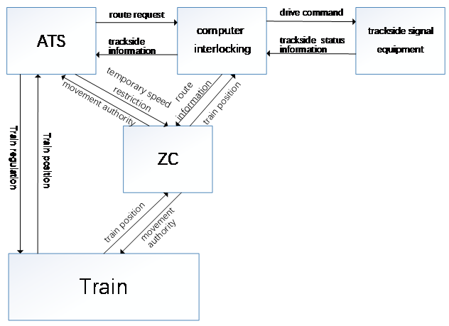
The Communication-Based Train Control System (CBTC) mainly includes automatic train supervision (ATS), a zone controller (ZC), computer interlocking (CI), a car borne controller (CC), a data communication system (DCS), and other subsystems, which is shown in Figure 1. Among them, the train automatically monitors the ATS to make the operation plan and supervise the train operation. The ZC manages all the trains on the line based on the information from CI and calculates the train moving authority (MA). The VOBC (including the Automatic Train Protection System (ATP) and the Automatic Train Operating System (ATO) receives the train operating clearance order from ZC and performs the train speed safety protection and automatic driving control. The DCS will ensure safe and reliable communication between the subsystems of the CBTC system. CI adopts advanced control technology to operate switches independently and improve the efficiency of line resources. The functions of the CBTC system are all based on the structure of “vehicle-ground-vehicle” for train interval control and speed protection. Because the system architecture is very complex and the communication link is relatively long, the probability of train failure is relatively high. The failure of any link will lead to a reduction in operation efficiency and even cause safety accidents [1].
|
Figure 1. The CBTC system. |
2.2. The CBTC system based on vehicle-to-vehicle communication
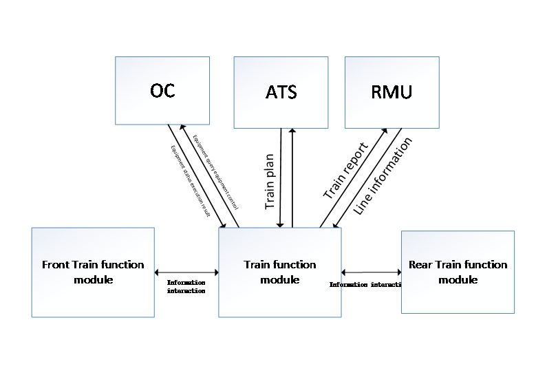
The CBTC system, which is based on vehicle-to-vehicle communication, designed with a train-centric concept. In order to avoid the shortcomings of long communication lines and a too complicated process, the system cancels the ZC and CI equipment, all the trackside equipment is controlled by an object controller (OC), and the ATS directly sends the operation information to the on-board equipment, which communicates directly with adjacent trains. Each train sends its own position information and obtains the position information of the vehicle in front to calculate its own authorized distance. When the train runs near the switch, it applies control to the OC corresponding to the switch so as to make the train move to the required position. This method makes the train directly control the trackside equipment, which better reflects the train-centric principle. Its system architecture is shown in Figure 2 [2].
|
Figure 2. The CBTC system based on vehicle-to-vehicle communication. |
3. The function module of virtual coupling
3.1. The function module of vehicle equipment
The realization of the virtual coupling function depends on the cooperation between the internal sub-functional modules and the external functional modules in the train control system of vehicle-vehicle communication. Therefore, we firstly design the internal sub modules of the virtual coupling function by analyzing the functional modules of the vehicle-vehicle communication train control system.
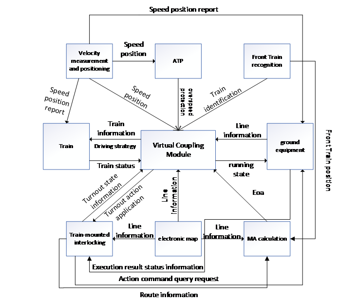
As shown in Figure 3, in the vehicle-vehicle communication train control system, functional modules of onboard equipment mainly include a speed measurement and positioning module, an electronic map module, a vehicle ahead identification module, a MA calculation module, a onboard interlocking module, etc. Next, we analyze the front vehicle identification module, the electronic map module, and the vehicle interlock module [3].
3.1.1. Front vehicle identification module. In the vehicle-to-vehicle communication-based train control system, the train adopts the moving block mode in the section. Within the section, the train tracks the tail of the only vehicle in front within a certain range in the same direction to complete the occupation and clearance of track resources. On the one hand, the identification module of the front car is responsible for the identification and tracking functions of the front car, and on the other hand, it responds to the request of the rear train for its position. The identification process includes the following: the train requests the information of other trains ahead from the RMU; the train initiates a broadcast communication to the train ahead; the position of the train in front will be compared and verified after receiving the position reply; This train establishes vehicle-to-vehicle communication with the only vehicle in front to get the position of the vehicle ahead; periodically verifies communication connection conditions; maintains communication links, etc. Among them, the successful verification and virtual coupling of the vehicle should be satisfied as following factors: the communication condition of this vehicle is normal; this vehicle and the leading vehicle are adjacent on the line; the distance between this vehicle and the leading vehicle is within the tracking range and communication range; and the leading vehicle does not actively disconnect the communication connection with this vehicle [3].
3.1.2. Electronic map. In the train control system based on vehicle-to-vehicle communication, the vehicle equipment is equipped with an electronic map module, including track line geographic information and fixed application data, which is the physical basis of train operation and satellite positioning. The geographical information data of the orbit line refers to the longitude and latitude data of satellite positioning in the orbit section. Fixed application data includes transponder and switch data. The data in the electronic map module provides the basis for the departure transponder and station positioning and the status judgment of the track section. The train will check the electronic map version during the electrical self-test. The electronic map version number applied by the train to the RMU is compared with the electronic map version number configured on the vehicle. If the version number is inconsistent, the train will apply to RMU for a new version of the electronic map to update the on-board electronic map [3].
3.1.3. Vehicle-mounted computer interlocking module. In the vehicle-to-vehicle communication-based train control system, we integrate the computer interlocking module into the vehicle, instead of the traditional ground interlocking. Its core function is still to line up routes for trains and extend safe routes. The first step to realizing route alignment function is route search to select a reasonable route. The traditional route alignment is ground interlocking based on a static look up of interlocking tables. This model has poor flexibility, universality, and portability. We perform topological abstraction on the signal layout diagram and combine the heuristic search algorithm of the diagram to search the path dynamically. The vehicle-mounted computer interlocking module in the vehicle-to-vehicle communication train control system is equipped with an interlock table and route search module at the same time, which has stronger compatibility and adapts to different requirements of route selection. The functions of vehicle-to-vehicle interlock in the vehicle-to-vehicle communication CBTC system mainly include: analysis of the dispatching plan, route control function, including resource status in query, route resource search, route resource control, and virtual signal control, and route unlocking function [3].
|
Figure 3. Information interaction diagram of train function modules. |
3.2. Ground equipment function module
The functional modules of ground equipment in a vehicle-vehicle communication train control system primarily include the RMU, the OC, and the ATS, which we also analyzed.
3.2.1. Resource management unit (RMU). The ground RMU is equivalent to the ground train information management database, whose main function is to record the train operation information and provide an information inquiry function for the train. Its specific functions include: the train management function, which determines over a certain range of trains, including train registration and cancellation, and train operation supervision; the line information management function, which stores electronic maps and line data for train inquiries and proofreading updates; and, in response to the train query function, assisting the train to complete the identification and route arrangement of the vehicles in front; the temporary speed limit management function, which receives the temporary speed limit information issued by the ground transportation capacity decision center and forwards it to the train. According to the function of RMU, the information interaction between RMU and train information mainly includes train registration, train deregistration, electronic map verification and update, other train position requests, and train periodic active reporting of running status [3].
3.2.2. Object controller (OC). The ground OC is responsible for managing switch resources. Its main functions are shown as following: switch resource status management, including switch resource status collection, storage, update and query, etc.; execute train action orders, and execute corresponding actions according to the operation orders of resource occupation and release issued by the train; switch resource allocation and virtual signal management. OC is divided into centralized OC and distributed OC. Their main difference lies in the control scope and functional logic. Distributed OC can only control one single switch or a group of double switches with relatively simple functions. It is mainly responsible for information collection and command execution but does not have the function of business logic. Centralized OC can control all switches in the range of simple stations or all switches in the upstream or downstream throat area of complex stations and manage virtual signals in the stations with a logical function of resource allocation [3].
3.2.3. Traffic dispatching module. The dynamic capacity decision system in the train control system based on vehicle-vehicle communication is mainly responsible for the dynamic operation decision. It has functions for train operation planning, temporary speed limit setting and sending, train operation supervision, automatic train operation data statistics and report generation, and other functions [3].
3.3. Ground equipment function module
Based on the functional requirement analysis of virtual train coupling and the architecture of the CBTC system based on vehicle-to-vehicle communication, the functions of the virtual coupling functional module are shown below [3].
3.3.1. Data transmission module. The virtual train coupling function requires the running information of adjacent trains on the line, including the current speed, acceleration, next stop, and other data. It also requires the RMU and OC to provide line information, including temporary line speed limits, base station electronic maps, and turnout ahead data. The data obtained from the internal calculation of the virtual train coupling also needs to be transferred to the respective on-board function modules to perform corresponding functions, such as the application of train turnout occupation and the transmission of train running information data. These data are received and sent by different on-board function modules, so the virtual coupling function module first needs to provide a data interface to exchange the required information [3].
3.3.2. Virtual coupling judgment module. When the train is in traditional operation mode, the virtual coupling function module of the train needs to analyze the current state of the train and determine whether the status of the line ahead allows the train to participate in the virtual coupling. At this time, the train is still in traditional operation mode and does not have the ability to analyze, verify, and calculate the operating conditions of the virtual coupling. Therefore, the functional module of the train’s virtual coupling needs to have an independent virtual coupling condition verification unit to meet the function [3].
3.3.3. Virtual coupling scenario identification module. Since the virtual train coupling has different processing schemes for different scenarios and the virtual coupling scenario is composed of the train information in the virtual coupling and the line information in front of it, neither the received line data nor the train running data can be directly used to determine the scene in the virtual train coupling operation mode. However, at present, there is no functional module in the on-board function module of trains aiming at the scene identification requirements of virtual train coupling, so the virtual coupling function module needs to provide a scene analysis and identification function module [3].
3.3.4. Virtual coupling scenario decision module. After the train completes scene identification, it is necessary to make decisions based on specific scenes to ensure the safety and efficiency of the train’s operation. How to improve the efficiency of train operation as much as possible under the premise of ensuring safety, especially in the mode of virtual train coupling, requires a lot of data and complex calculations to ensure. Therefore, this part is a separate scene decision function module [3].
3.3.5. Virtual coupling operation module. The virtual coupling operation mode has a very high requirement for automatic train operation control. The traditional automatic train operation control algorithm is not applicable in the scenario where the speed interval is required to be very precise, so there must be a separate train operation control function module in the virtual train coupling function module [3].
4. Virtual coupling operation scenario of vehicle-to-vehicle communication
4.1. Normal scenario
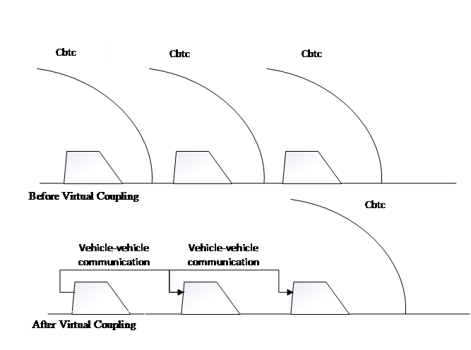
Virtual coupling enables the rear vehicle to obtain the running state of the front vehicle through direct wireless communication between vehicles so as to control the running of the rear vehicle. In this way, the front and rear cars are connected, as shown in Figure 4. The connection mode is changed from mechanical to wireless communication. In the virtual coupling operation, trains with different train numbers leave the station and are connected without stopping through the virtual coupling technology in the interval, and the train running interval becomes smaller. When the train needs to operate in different sections of the front station, the train control running interval becomes larger before entering the station, and dynamic uncoupling is carried out[4]. From the point of view of the signal system, before virtual coupling, the on-board equipment of each train controls the train according to the running permission of the CBTC train control system. After virtual coupling, the on-board equipment of the vehicle in front should still control the vehicle with the driving permission of the CBTC-level train control system, and the position of the vehicle in front should be determined by the identification module of the vehicle in front. When the speed of the rear vehicle is lower than that of the front vehicle, the data transmission module is used for data transmission, and the decision is made after judgment and scene identification. Finally, the decision module makes the operation control module speed up to reduce the operation interval. When the speed of the vehicle behind is higher than that of the vehicle in front, it runs at the same speed as the module in front and finally achieves its purpose of slowing down the train. When the rear vehicle scene decision module finds that uncoupling is needed, the rear vehicle data transmission module sends a request for uncoupling, the front vehicle agrees to the request, and the rear vehicle starts braking. After disassembly, the running interval between the rear vehicle and the front vehicle becomes larger, and the on-board equipment of the rear vehicle recovers to be controlled by the driving permission of the CBTC-level train control system [4].
|
Figure 4. The running scenario in virtual coupling. |
4.2. Fault scenario: interrupted vehicle-to-vehicle communication
The initial interval between train 1 and train 2 is d, train 1 runs at speed V1, and ATS sends the running plan command to make the two cars enter the virtual coupling mode. Train 2 enters the virtual coupling mode after receiving the instruction and tracks the rear of train 1 through the identification module of train 1. The speed of the virtual coupling target is V1, and the safety interval of the virtual coupling target is D.
(1) Before train 2 fails to reach the virtual coupling target, the communication between vehicles is interrupted. Train 1 was running at the original speed, but trains 1 and 2 failed to send requests to the RMU virtual coupling.
(2) After reaching the virtual coupling goal, the communication between the two vehicles is interrupted at time T. Train 2 finished virtual coupling, and train 1 ran at the same speed. However, at time T, the vehicle-vehicle communication was interrupted, and the ground equipment resource management unit (RMU) collected information and reported it to the ATPs of the two vehicles. Train 1 keeps the original speed unchanged and continues to run. The scene identification module of train 2 judges the interruption scene, and the decision module sends an instruction to train 2. The operation control module makes train 2 slow down and then triggers emergency braking to stop [4].
4.3. Safety measures in the fault scenarios
In order to avoid serious accidents in vehicle-to-vehicle communication, we design safety protection from the aspects of hardware, safe communication protocol, and network security.
4.3.1. Hardware security measure. In terms of hardware design, the system can adopt a double two-out of-two safety computer platform. The fault tolerance and safety management unit are in charge of managing the platform’s working state and mode. According to the different working states of the whole system, it can be divided into a “working” state and a “non-working” state [5]. The “working” state includes “primary” and “secondary” modes. The non-working status includes four modes: power on, fault, synchronization, and maintenance. The fault-tolerant and safety management unit monitors the operating status of the application processor and sends a mode code to the application processor to notify the operating mode. At the same time, the fault tolerance and safety management unit realize the interaction between the two systems through self-locking or interlocking logic. The coordination and management of the design and implementation mode of the two-by-two secure computer platform can avoid the state of “double primary” or “double secondary” modes when the two channels judge each other, so as to ensure the safe and reliable realization of the state switch of “primary” and “secondary” channels [5].
4.3.2. Safe communication protocol. At present, two safe communication protocols are used for data transmission among railway signal safety equipment in China: the RSSP-I protocol and the RSSP-II protocol. When safe information is exchanged between signal devices through a closed transmission system, the RSSP-I protocol is used. The RSSP-II protocol is used for security information exchange between signal devices through an open transmission system. RSSP-I uses TCP/UDP and serial port transmission. In the closed transmission system, there are communication threats such as “duplicate”, “delete”, “insert” and “reorder”. In order to reduce the risk of related threat sources, the RSSP-I protocol considers the security of the transmitted information at the receiving end and designs a protection algorithm from the perspective of the receiving end [6]. The receiving end verifies the data characteristics of the received messages. RSSP-II adopts TCP transmission mode and uses an encryption and authentication algorithm in an open environment for security link establishment. According to the actual requirements of the project and the characteristics of the system design, we flexibly adopt two kinds of secure communication schemes [6].
4.3.3. Network security measure. The protection of secure communication networks focuses on the design of signal system architecture, the redundancy of network bandwidth resource distribution, and the reasonable division of network security areas. The division of security zones should be based on the logical correlation, service characteristics, and physical locations of subsystems of the signal system. There is data interaction among all railway signal systems and levels. If service data is directly transmitted through unprotected protocols, there is a high risk of network intrusion and virus transmission. In accordance with horizontal isolation, we need to deploy security at the system boundary. We need to establish a unified management of security components, a unified monitoring of the whole network system components, and a security management center with a situational awareness function to realize centralized monitoring of the running status of key components of the CBTC system based on vehicle-to-vehicle communication and summarize the existing security events in the system for display, processing, and emergency response.
5. Conclusion
Based on the CBTC system, a novel train control system based on vehicle-to-vehicle communication is proposed in this paper, and the components of the system that realize the function of virtual coupling are designed in a modular fashion, and the normal and abnormal scenarios of virtual connection are analyzed in depth. Compared with the CBTC system, the CBTC system based on vehicle-to-vehicle communication and virtual coupling can streamline trackside equipment, improve signal system response time, improve train operation efficiency, reduce operation and maintenance costs, and meet more new operation requirements. To some extent, it can improve the intelligence level of the whole railway industry, which is one of the development directions of the next generation rail transit safety control system.


