


1. Introduction
As we all know, the development of the automobile industry has brought huge pollution to the environment. Relevant data shows that US automobile emissions account for 60% of the total urban pollution share [1]; China has also accounted for 25% to 40%. About 40% of the greenhouse effect in large cities comes from vehicle exhaust emissions [2-3]. The main fuels used in cars are gasoline and diesel, both of which are extracted from petroleum. However, oil is not renewable, and mankind faces energy challenges. Seeking new green energy to replace traditional petroleum products is an effective way to reduce automobile pollution in the environment and deal with the energy crisis. The US and China have abundant solar energy resources, and the application of solar energy to automobiles has very broad prospects, so it has received extensive attention from the international community [4].
Solar energy is the radiant energy generated and emitted by the sun. It is transferred in the form of electromagnetic waves through outer space to the Earth [5-6]. Part of the incident solar energy is reflected and absorbed by Earth’s atmosphere, while the rest reaches Earth’s surface, where it can be converted to heat, chemical energy (in the form of photosynthesis), and electricity. Solar energy also has lots of advantages. The sun generates vast amounts of radiant energy and transfers it to Earth [7-8]. It is the largest energy source available in our solar system. By some calculations, the amount of solar energy reaching the Earth in one month is equivalent to all the energy of all fossil fuels on Earth, both already consumed and unused [7, 9]. Solar energy is nuclear energy without the drawbacks of nuclear energy: the thermonuclear reaction's chemical and radioactive byproducts remain on the sun, while only pure radiant energy reaches the earth [10].
Today, in the field of solar vehicles, there are still many problems to be solved [10]. And how to ensure that the solar panels on the car's surface can withstand the various influences caused by the flow of high-speed gas while still working efficiently when the car is running at high speeds is an important topic of discussion [8, 11].
On the basis of consulting a large number of materials, this paper models the most commonly used solar panels with COMSOL software and simulates and studies the streamline distribution, velocity distribution, pressure distribution, and stress distribution of the solar surface under the high-speed movement of 90km/h. Based on this data, a vehicle body structure for future solar cars is designed by using SoildWorks simulation. The streamline distribution and pressure distribution of the car body at a high speed of 90km/h are simulated and studied in FLUENT software. Finally, the rationality and feasibility of the design are verified. The research presented in this paper provides a preliminary model idea for the body structure design of a new type of solar vehicle that may be applied in the future. The author believes that in the near future, with the gradual improvement of all aspects of solar energy technology, the market for new energy vehicles will become larger and more promising.
2. Simulation Research on Solar Panels at High Speed
2.1. Dimensions and structural parameters of solar panels used in the study
The structural parameters of the solar panel, which are the most important part of the solar car, play a decisive role in this study. This paper studies the periodic flow field formed around an array of solar panels, each of which is located in a regularly distributed array of panels and is subjected to strong oncoming winds; see Figure 1. The model simulates structural displacement due to flow and fluid loading around the panels. It is assumed that there are enough panels installed upstream and downstream of the panel so that periodic flow conditions apply in the flow direction. Viewed from a height, the solar panel array acts as a rough boundary for the flow of the atmosphere.
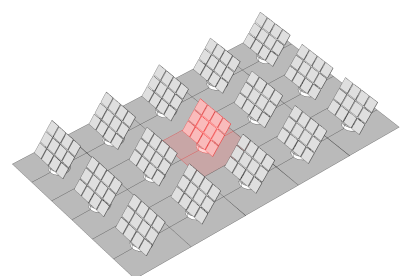


Figure 1. The simulated solar panels (red) located in an array formed by a regular arrangement of identical panels
The current simulation research needs to achieve two goals:
(1) Solve the fluid flow around the solar panel with a free velocity of 25 m/s (90 km/h) above the panel.
(2) Study the solar panel's deformation caused by fluid load.
In the model, the same geometry is used for fluid flow modeling and subsequent structural mechanics simulation. Figures 2 and 3 show the solar panel geometry. More specifically, Figure 2 shows the front of the solar panel, facing in the direction of incoming flow, and Figure 3 shows its back.
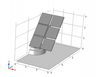
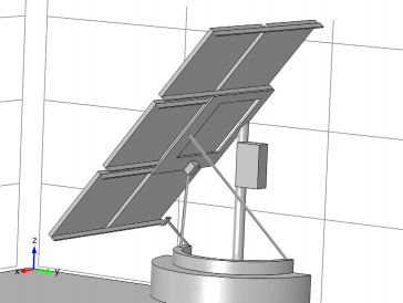
Figure 2. Front view of solar panel geometry Figure 3. Rear view of solar panel geometry
Its global structure parameters are shown in Table 1 below:
Table 1. Global structure parameters
Name | Expression | description |
Utop | 25m/s | Top Speed, Couette Flow |
yLen | 6m | Border length along the flow direction |
yEnd | 4m | Border end point along the flow direction |
2.2. Model solution strategy
The model uses two different studies: one using the Turbulence k- \( ε \) physics interface to solve for turbulence around the solar panel, and the other using the Solid Mechanics interface to solve for structural stresses and displacements. The Fluid-Structure Interaction, Fixed Geometry multiphysics coupling feature is used to couple boundary loads due to fluid flow from the fluid domain to the solid domain, equivalent to a unidirectional fluid-structure coupling analysis.
2.2.1. Fluid Flow Simulation. In the fluid flow section, the goal is to simulate the flow field above the solar panel with an incoming velocity of about 25 m/s. This is equivalent to a 10 on the Beaufort scale with a ground condition of "broken or uprooted tree; considerable structural damage". The Reynolds number based on panel structure height and incoming flow velocity is about 6.6 106. These conditions create very complex flow fields. To obtain a converged solution, the following modeling steps are used:
(1) Define the fluid flow geometry high enough to capture boundary layer flow reaching above the solar panel array; see Figure 4. Use a mapped mesh in a solar panel and refine the fluid domain to resolve the flow field.
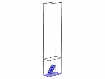
Figure 4. Calculation box used in fluid flow simulations.
(2) Periodic flow conditions are used to specify the pressure differential in the flow direction, ensuring an average velocity of 25 m/s at the top of the panel.
(3) Ensure that the first iteration of the nonlinear solver converges by adding an isotropic diffusion that is inversely proportional to the number of CFLs (for pseudo-time stepping).
2.2.2. Structural Mechanics Simulation. In a structural mechanics simulation, we apply the fluid loads calculated from the fluid flow simulation to the solar panel structure and then solve the model to obtain the structural stresses and displacements. The Fluid-Structure Interaction, Fixed Geometry multiphysics coupling feature is used to couple the total fluid stress on the panel surface from the flow simulation to the structural simulation. The author added a "Safety" subnode for checking the risk of failure of different materials for solar panels.
2.3. Simulation Results and Discussion
2.3.1. Velocity profile of the computational grid. The velocity profile of the computational grid is shown in Figure 5:
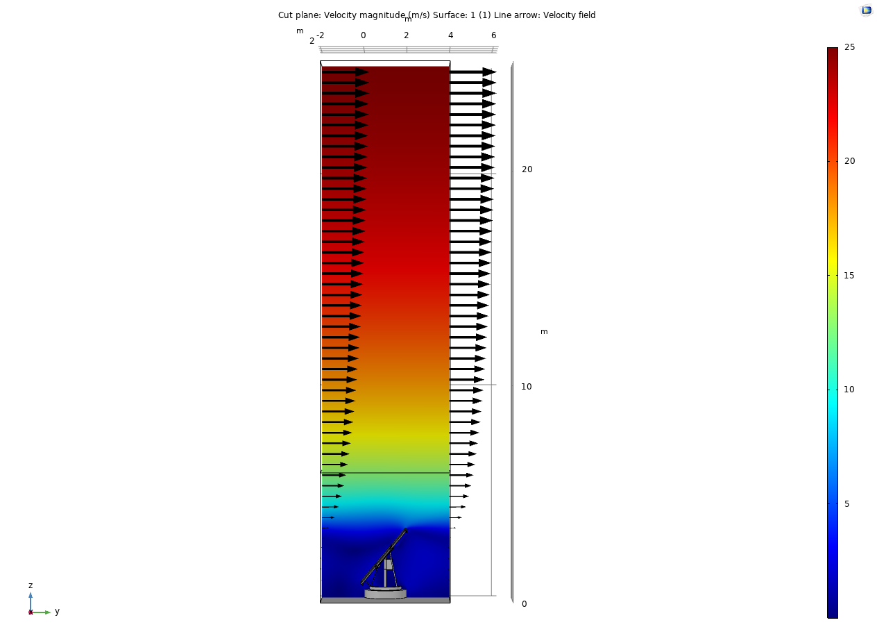
Figure 5. Velocity magnitude
This is a surface plot showing the flow velocity distribution on the center plane of the solar panel, with the velocity vectors for the inlet and outlet plotted. The flow field above the panel is the boundary layer flow field, and the maximum velocity of the free flow is 25 m/s, which is reached at the top of the computational element. The velocity of the solar panels in the periodic flow field near the panels is also significantly reduced due to being hindered by the panels placed at the lower end. Therefore, it can be said that the flow field is equivalent to a rough-walled turbulent boundary layer flow field, where the solar panel acts as a rough element.
2.3.2. Pressure distribution. The pressure distribution of the surrounding high-speed fluid on the solar panel structure is shown in Figure 6, and the eddy current distribution behind the solar panel is shown in Figure 7.
style='position:absolute;left:0pt;margin-left:284.05pt;margin-top:25.65pt;height:33.3pt;width:36pt;z-index:251660288;v-text-anchor:middle;mso-width-relative:page;mso-height-relative:page;' />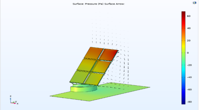
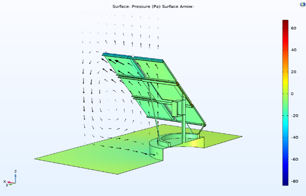
Figure 6. Pressure distribution Figure 7. Distribution behind the solar panel
The relative pressure in the upper right corner of the panel is the largest, at about 70 Pa. From the velocity component of the plane perpendicular to the flow direction plotted in Figure 7, the reason for the highest pressure in the upper right corner can be found: a large vortex is generated behind the panel, the center of which is flush with the outside of the panel. In the upper right corner, high pressure is associated with a large deflection of the flow and the formation of a vortex.
2.3.3. Surface deformation and safety factor. This paper focuses on the analysis of structural stress and safety factors of solar panels. The bracket part will not be installed under real vehicle conditions, so ignore its influence.
The strain and safety factor analysis of the solar panel is shown in Figures 8 and 9.
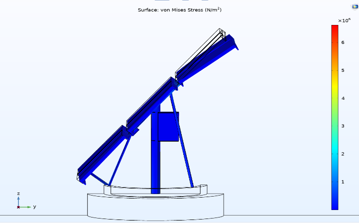
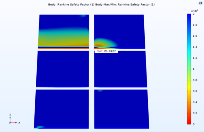
Figure 8. Deformation of the solar panel surface Figure 9. Solar panel safety factor calculation
2.3.4. Streamline distribution of fluid. The flow around the solar panel is analyzed in Figure 10, showing the streamlines originating from the inlet. Note that some of the streamlines near the center of the solar panel enter this area and then turn away, indicating that there is a circulation zone between the panels in the array. Streamlines are colored according to the magnitude of the local turbulent kinetic energy, where the turbulent kinetic energy is normalized using the kinetic energy of the mean flow. The kinetic energy is lower in the circulation zone in front of the panels than in the wake behind. This is expected as they are part of the same flow structure. Turbulent kinetic energy increases with distance from the ground, especially when flowing over the top of the panels. The higher kinetic energy distribution and mean velocity gradient at this location are shown in Figure 10.
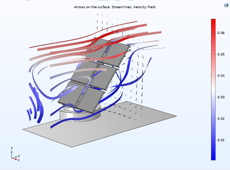
Figure 10. Streamlines around solar panel
2.3.5. Partial summary of solar panels. The above part of the simulation studies the oncoming pressure, surface pressure, pressure distribution and streamline distribution in the calculation area of a single solar panel when the simulated vehicle speed is 90km/h. Because in the case of a real car, multiple solar panels will be closely attached to the surface of the vehicle body, so if the model assumption is to be established, the most important factor to consider is the pressure generated by the fluid on the solar panel at high speed, and its surface Deformation under stress.
In the next chapter, this paper will combine the above simulation results to design a solar car body frame structure and verify its feasibility through FLUENT software.
3. Body structure design of solar car
3.1. Modeling and meshing of the body as a whole
The design of the solar car body in this paper refers to Figure 11.
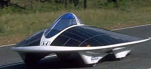
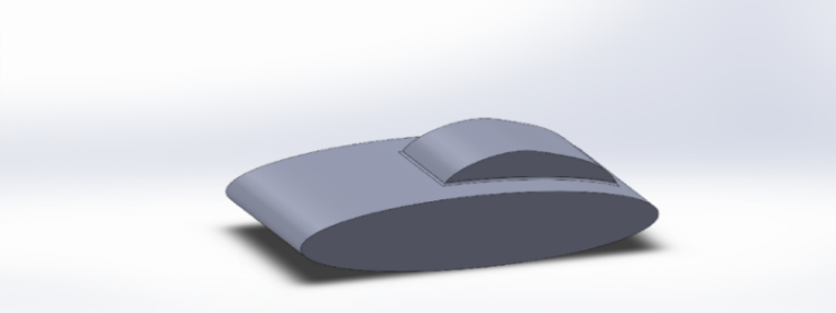
Figure 11. Solar energy car [12] Figure 12. Overall body design sketch
As shown in Figure 12, it is based on the body structure design of a new type of solar car that may exist in the future. Figure 13 shows the overall meshing of the simulated duct simulation experiment for this model. It is divided into 272722 nodes and 1426887 elements.
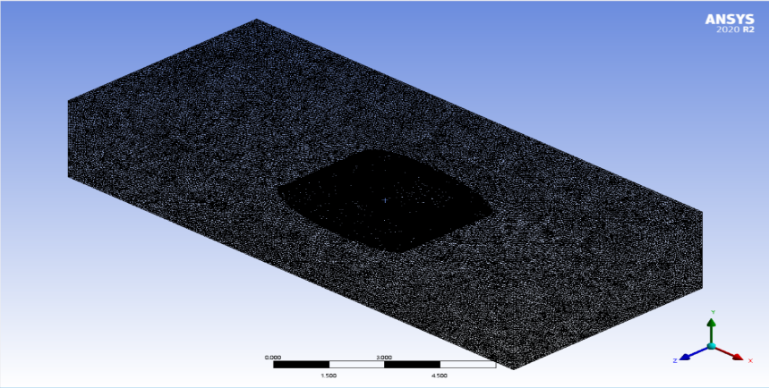
Figure 13. Meshing
3.2. Body Surface Fluid Flow Simulation
The fluid flow adopts the k-ε model, the fluid is incompressible, and the body surface has no slip. The schematic diagram of the fluid flow simulation is shown in Figure 14.
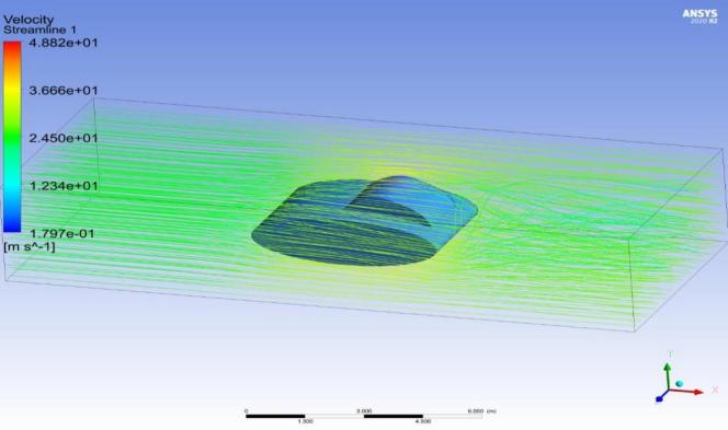
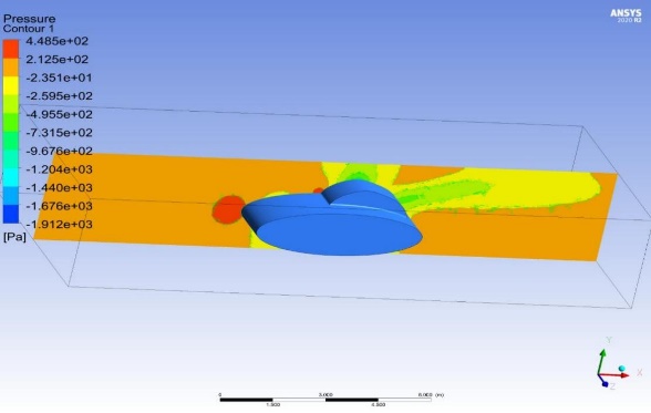
Figure 14. The fluid flow on the body surface Figure 15. Body surface pressure
As can be seen from Figure 14, the streamlined structure of the body surface greatly reduces the resistance of the oncoming fluid, and improves the efficiency while ensuring the overall size.
The pressure generated by the fluid on the entire body is shown in Figure 15.
It can be seen from the pressure distribution on the surface of the vehicle body that solar panels can be installed on other parts of the upper surface of the vehicle body except that the pressure generated by the windward part of the body head and the connection between the cockpit and the vehicle body is too large to install solar panels. To ensure that it can operate effectively and will not produce excessive deformation. Therefore, it can be considered that the designed body can be used in future solar cars.
4. Conclusion
In this paper, the COMSOL software is used to simulate and study the pressure generated by the fluid and the deformation caused by the pressure of the existing solar panel under high-speed motion, and it is further simulated and designed a body that may be suitable for future solar cars, and it uses FLUENT software to conduct a simulated air duct study on the body surface at 90km/h, verifying the feasibility of this body. But the biggest problem with this paper is that the real vehicle test cannot be carried out, and everything is only the data obtained by computer simulation. In the case of a real vehicle, there are still many things to consider, such as the outdoor temperature, the roughness of the ground, and the viscosity of the air. Therefore, the simulation only provides an idea for future new energy vehicles, but to turn the idea into reality, more experiments are needed to support it.