1. Introduction
The new automobile brake system is different from traditional automobile, its brake power and brake control device are more novel and efficient, and response speed and braking effect are more prominent, so most automobile manufacturers are vigorously developing new automobiles, optimizing the design of their electronic mechanical braking system, and achieving performance and device improvement of new automobiles through simulation experiments. In the current development of automotive science and technology, the main forms of line control are Electro Hydraulic Brake(EHB) and Electro Mechanical Brake(EMB). The EHB replaces the vacuum booster, but the EHB is not easy to integrate with other electronic control systems. The EMB is the electronic mechanical line control, which improves the response speed, has simple structure, flexible control and higher efficiency [1].
With the development of new energy vehicles, car ownership will continue to increase, and the safety problems caused by it will become more and more serious, and the direct embodiment of car safety performance is the braking system. The brake system of automobile is easy to form a gap under the action of external force in the process of driving, which leads to the decrease of braking force, resulting in serious vehicle safety problems. The optimization and improvement of the braking system has become one of the research hotspots, and the braking deceleration when the wheel is locked can be reduced through a practical and effective electro-mechanical braking system to improve the safety of the vehicle on the move [2]. EMB is the ideal brake actuator for high-level autonomous driving technology, which meets the needs of the development process of autonomous driving and low-carbon vehicles [3].
This paper mainly analyzes and compares the vacuum booster and Electro-Mechanical braking system, and puts forward the advantages of the latter in the present and future practical application significance. Under the current energy and environmental crisis, new energy vehicles have become an important direction of automobile development. New energy vehicles not only have emission reduction advantages in the energy sources used but also can use new technologies to further improve energy conservation and emission reduction effects. Regenerative braking technology is one of the key technologies.
2. Vacuum booster
This chapter mainly outlines the structure of the vacuum booster, which mainly includes control valves, springs, plungers, etc., and its working principle is to use vacuum (negative pressure) to increase the force exerted by the driver on the pedal.
2.1. Traditional vacuum booster design
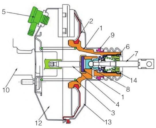
As shown in Figure 1, the traditional vacuum booster designs consist of an air control valve(5), return spring (3), plunger (8), piston (1), diaphragm (2), etc.

Figure 1. Structure of vacuum booster.
2.2. Working principle of vacuum booster
When stepping on the brake, the foot torque is amplified by the lever, acting on the air valve stem of the maximum vacuum booster, and the valve stem reverse spring is compressed to drive the air valve seat forward, and through the feedback disc and the hydraulic system, the air brake moves to the first piston of the main cylinder, thus forming the hydraulic pressure, the opening torque of the brake wheel cylinder, promoting the brake shoe to form the braking force.
At the same time, the rubber valve part moves with the real air seat under the action of the valve stem spring, closes the maximum vacuum valve port, separates the front and rear cavities, and cuts off the front and rear air chambers and the maximum vacuum source. (This is an instant process)
Due to the continued movement of the valve stem, the gas valve and the rubber valve are separated, the internal gas valve port is restarted, and the external gas flows into the rear cavity through the foam filter element, the inner hole of the rubber valve and the large empty valve outlet, so that the pressure difference between the front and back two cavities is formed, and this pressure difference forms an interaction between the key components such as the diaphragm of the booster and the power plate. In addition to a small part of the resistance and working pressure difference as a balance spring, it mainly acted on the feedback disc through the valve body and then transmitted to the brake master cylinder. During this process, the vacuum valve port is always kept in the closed position.
In the process of pressing the pedal, the valve stem is pushed forward, the compressed air continues to flow into the rear air chamber through the open rear air valve port, and the valve body continues to move forward. When the pedal stops in a balanced position, the valve body will move to the vacuum valve port closed place, the time and space valve port and the vacuum valve port are in a closed position, while the auxiliary is maintained a balanced position, that is, the valve column pressure, the servo torque generated by the front and rear air room, and the driving force generated by the main cylinder hydraulic system (the auxiliary output force of the reaction force) balance each other.
At present, the pressure difference of the rear cavity has reached the maximum, that is, after the pressure difference of the rear cavity is completely equal to the atmospheric pressure, the vacuum power is maximum, and then, even if the change of the inlet pressure and the change of the outlet pressure is the same, there is no increase in servo pressure.
Release the brake pedal, and the stem reversing spring immediately pushes the vacuum seat of the stem back, so that the vacuum valve port is completely closed, the vacuum valve is opened, and the key components return to the starting position under the guidance of the return spring, and the booster returns to the non-target position [4-8].
3. Electro-Mechanical Breaking System
In this section, the structure and working principle of the Electro-Mechanical brake system are summarized.
3.1. Design of Electro-Mechanical Braking System
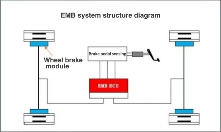
Electro-Mechanical braking system as a form of BBW line control system, in addition to a new electronic control brake, as well as its new braking system. Electro-Mechanical breaking System has 6 basic components: an independent electronic brake mounted on 4 wheels, a brake pedal simulator, a central control unit, an electronic brake controller, wheel speed, speed, and other sensors, and a power supply system, as shown in Figure 2.

Figure 2. Schematic diagram of EMB system structure.
The corresponding braking signal is sent to the four controllers, and the controller will control the four motors to brake the four wheels independently after receiving the signal. Through the sensor, the actual braking torque and other information of each brake is fed back to the central control unit to form a closed-loop control to ensure the best braking effect. The braking force and braking time of the electronic brake are controlled by the central control unit, so it is only necessary to write the program of ABS, TCS, ESP, and other functions into the central control unit, without adding additional hardware equipment, and various braking safety control functions can be realized centrally. This shows the superiority of modularization and integration of wire control systems [9].
3.2. Principle of Electro-Mechanical Braking System
The working principle of the new automotive Electro-Mechanical braking system can be summarized as follows: when the driver's footsteps on the pedal, the pedal sensor will recognize the situation and the driver's relevant data, such as the strength of the foot, and then transmit the data processing to the central electronic control element, analyze the driver's intention and braking demand through the EUC, and then transmit the processing results to the execution structure. And communicated to the wheel brake, so that the car according to the driver's intention and operation drive. In the process of signal transmission, the three-ring speed regulation system and the motor shaft will be rotated to ensure that the motor can successfully send the signal to the rotating structure under the influence of the output armature voltage, realize the speed signal transformation under the deceleration and increase of the distance, and complete the braking transformation under the brake mechanism [10]. In the whole process, rapid response and execution are needed, so the automobile brake system has changed from the original drive-by-wire control to the current electronic type to speed up signal transmission and analysis, and quickly complete the automobile drive and brake. At present, the time of the entire automobile’s electronic mechanical brake system is controlled at about 0.1S to meet people's demand for automobile performance [11-13].
4. Comparison and result analysis
By comparing the vacuum booster and the Electro-Mechanical braking system, this chapter points out the advantages of the EMB compared with the vacuum-assisted pump, and the current research status and research significance of EMB.
4.1. Comparison of two devices
The traditional vacuum booster completely relies on the engine to run and inhale to form a vacuum to achieve brake power. The typical characteristic is that if the engine is turned off, the vacuum help will soon fail. At this time, the braking ability is greatly reduced. If the brake pedal is not stepped on, the natural braking effect is difficult to ensure [14]. The Electro-Mechanical braking system completely relies on the motor to generate power to promote the work of the brake master pump. When stepping on the brake, the pedal travel sensor feels the brake pedal depth, and the electronic control unit comprehensively analyzes the driver's intention, and commands the power motor to operate, and then promotes the brake pump to complete the braking action. The whole brake system is basically electronically controlled to complete, does not need the engine vacuum, and for electric vehicles is undoubtedly the most suitable.
Vacuum booster is prone to defects such as wear and misadjustment, which will cause safety hazards to vehicle driving [15]. Electro-Mechanical braking systems can control wheel braking through electronic signals to achieve a more accurate, rapid, and stable braking effect, and at the same time avoid overheating, wear, and other problems of the brake [16].
4.2. Advantages of Electro-Mechanical braking system
Electro-Mechanical braking system uses electric energy as an energy source, the Brake pad is driven by the motor, the energy is transmitted by the wire, and the data line transmits the signal, which is a form of brake-by-wire system. Electro-Mechanical braking system is a new braking concept. Its simple structure and efficient performance greatly improve the braking safety of vehicles [17]. The Electro-Mechanical braking system has the following major advantages over traditional hydraulic braking systems.
a. Less mechanical connection, no brake pipe, simple structure, small size.
b. The load transfer is smooth and soft, and the braking performance is stable.
c. Mechanical and electrical connection, rapid signal transmission, sensitive response, "road sense" good.
d. High transmission efficiency, and energy saving.
e. Electronic intelligent control is powerful, you can modify the software in the ECU, configure the relevant parameters to improve the braking performance, easy to achieve ABS, TCS, ESP, ACC, and other functions.
f. Modular structure is more integrated, simple assembly, and convenient maintenance.
g. Conducive to environmental protection, no hydraulic brake lines and brake fluid, no hydraulic oil leakage problem, EMB system has no non-recyclable parts, almost no pollution to the environment.
4.3. Usage Meaning of Electro-Mechanical Braking System
The research on Electro-Mechanical braking systems is very important. This is a key area of future automotive braking technology that will make a significant contribution to safe, reliable, and intelligent driving. Electro-Mechanical braking system is the use of a motor to replace the traditional compressed air or hydraulic, mechanical drive can effectively improve the braking energy efficiency and the corresponding speed, and it can also through an electronic control system to simplify the operation, which is conductive to the vehicle driving.
Compared with the traditional vacuum booster pump, the braking efficiency of the Electro-Mechanical braking system is more prominent. Electro-Mechanical braking systems can replace the traditional vacuum booster pump and meet people's requirements on automobile performance and mechanical braking [18]. However, at this stage, ESP, ABS, and TCS are still added to the traditional compressed air or hydraulic braking system to meet the performance requirements of mechanical braking, which leads to a more complex mechanical pipeline layout and structure, increasing the safety risks of hydraulic and compressed air, which is not conducive to maintenance and assembly operation. It is the future development direction of the automobile industry to design an Electro-Mechanical braking system that meets the demand of new automobiles [19].
5. Conclusion
In this paper, the structure and principle of traditional vacuum booster and Electro-Mechanical brake system are enumerated, and then the two devices are compared, and the advantages and disadvantages of each are expounded. In today's era of more and more new energy vehicles, the use of EMB is also more and more, its main advantages are such as high transmission efficiency, energy saving, simple assembly, easy maintenance, and so on. EMB is the use of a motor to replace the traditional compressed air or hydraulic, mechanical drive can effectively improve the braking energy efficiency and the corresponding speed, but also through the electronic control system to simplify the operation, conducive to vehicle driving. At this stage, with the gradual attention of the energy crisis and the rapid development of the economy, people have new requirements for the performance and energy consumption of automobiles. In order to meet the needs of market development, countries are strengthening the research and development of vehicle wire control systems, one is to improve the safety performance and performance of automobiles, and the other is to improve the response speed and efficiency of automotive mechanical braking. Reduce maintenance and assembly difficulty. The structure of EMB is more compact and complex, so it is more difficult to establish the simulation model. Therefore, the focus of the research is to verify the rationality of the EMB system. After the design of the EMB, it is necessary to use the simulation model to conduct a comprehensive analysis of the designed EMB system and provide a reliable basis for its application.


