


1. Introduction
As a form of alternative medicine, low frequency electrotherapy employs the use of electrodes to transmit pulses of low frequency and low voltage to treat a variety of conditions. Neuromuscular electrical stimulation therapy, transcutaneous nerve electrical stimulation therapy, interkinetic electrotherapy, low-frequency high-voltage electrotherapy, etc. are all examples of low-frequency electrical therapies currently in use[1]. The absolute refractory period of mammalian motor neurons is typically around 1ms, and the pulse frequency of 0 to 1kHz is a low-frequency current. Consequently, every sub-1 kilohertz pulse current may activate a motor [2]. In most cases, their voltage is below 100V and their current is below several milliamps. Triangular waves, acute waves, square waves, trapezoidal waves, and so on are all examples of the various varieties of positive waves. Pulses can either go in one direction or back and forth between two points [3]. The clinical applications and significant benefits of low frequency pulse electrotherapy are extensive. As a bonus, it can be used to treat and prevent nerve-related motor dysfunction in the limbs and disuse atrophy in otherwise healthy muscles. It can also improve circulation, reduce pain, and stimulate the nervous system [4]. Low-frequency electricity's analgesic impact has a special place, and it's been put to extensive clinical usage. The suffering and stress that pain causes in patients has made finding effective treatments a pressing area of study in the modern world [5]. Since low frequency electrotherapy is so easy to use, portable, and effective, it can be implemented in a wide variety of clinical settings for the treatment of various diseases. This treatment option has the potential to be helpful because it is easily accessible and relatively inexpensive [6].
An abundance of models and different kinds of development boards give Arduino a wide range of available products. As a result of its adaptability, the first generation Arduino UNO development board is the best choice for this project. The experiment uses an Arduino UNO R3 development board because of its I2C bus interface, reset circuit, 13 digital output pins, integrated protection circuit, and pulse generation indication. And two energy ports, one each at 5V and 3.3V, that can deliver power at a controlled voltage, making it possible to run certain low-power microcontrollers. For this project, we used an Arduino UNO board, with one energy port dedicated to powering the control circuit, five digital ports showing the circuit's inputs and outputs, and a sixth digital port for delivering electrotherapy shocks.
This experimental design is important because it suggests a simple, low-risk way to construct an electrotherapy device. Because both the circuit and the code are so easily modified, using Arduino to construct the electrotherapy instrument can significantly cut costs throughout the development stage. Arduino's contributions to the field of healthcare electronics have allowed for greater personalization in this sector. Avoid pain triggers, seek professional medical care when necessary, and apply sound medical and scientific principles to alleviate suffering and restore function [7].
2. Main circuit
The power supply in this design can be either a USB cable or a 9V battery. Button power comes from 5V supplied by the bread board, which is supplied by the energy port of the Arduino UNO development board. The ground (GND) pins of the five buttons are connected to one of the GND ports on the development board, which is in turn connected to the other side of the bread board. The high-level signal sent from the button in the control circuit to the development board is detected and received by the pins 2, 3, 4, 5, and 6 on the other side of the Arduino UNO board. A signal is sent out from pins 8, 9, 10, and 11 on the same side of the digital port of the development board to turn on the corresponding LED indicator in the pulse indication circuit; pin 13 and the remaining GND ports are first connected to two booster circuits, and then applied to the output of electrotherapy impulses after amplification.
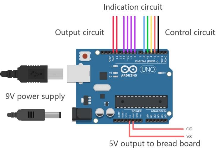
Figure 1. Development board pin allocation (made with Tinker CAD).
3. Control and indication circuit
When activated, these buttons will broadcast a strong signal and promptly reveal themselves. Pushing the red button initiates the instrument's pre-operational phase. Then, in order (shown in figure 2), push the yellow, green, and blue buttons to cycle through the electrotherapy's low, medium, and high settings. In the event that the black button is touched while the circuit is active, the instrument will turn off, cease to emit impulses, and render all other buttons ineffective until the red button is pressed again. Each of the four LED indications and their related 100 protection resistances represent either the on or off position, as well as the high, medium, or low intensity of the electrotherapy output.
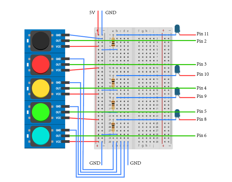
Figure 2. Control and indication circuit.
Once the pulse is made, it is fed into the first of two AC boost circults in the figure 3 below, and then the equivalent frequency bidirectional pulse is made and sent out to the electrodes. Having two independent boosters allows for more accurate and controllable voltage change and can affect circuit protection in a positive way.
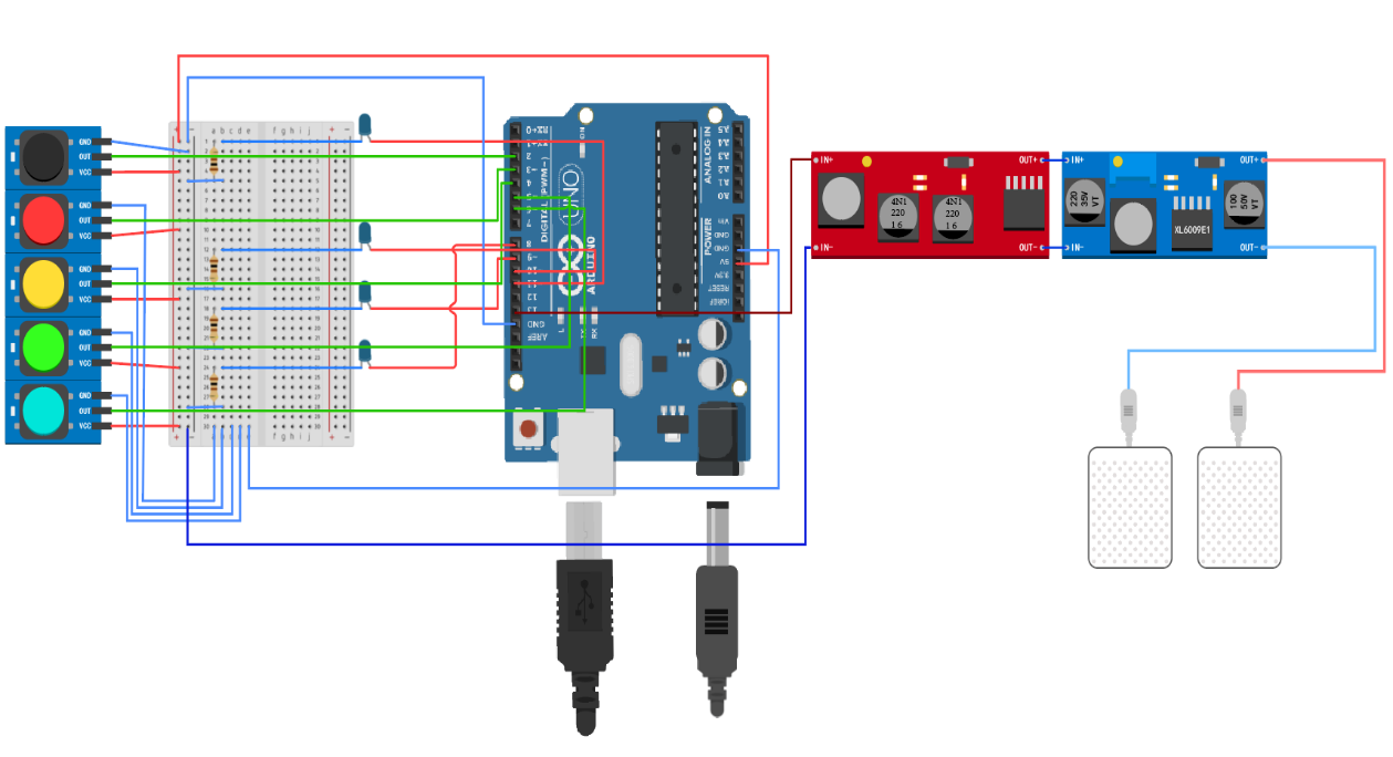
Figure 3. Main circuit.
The flow chart of the software part is shown in the figure 4.
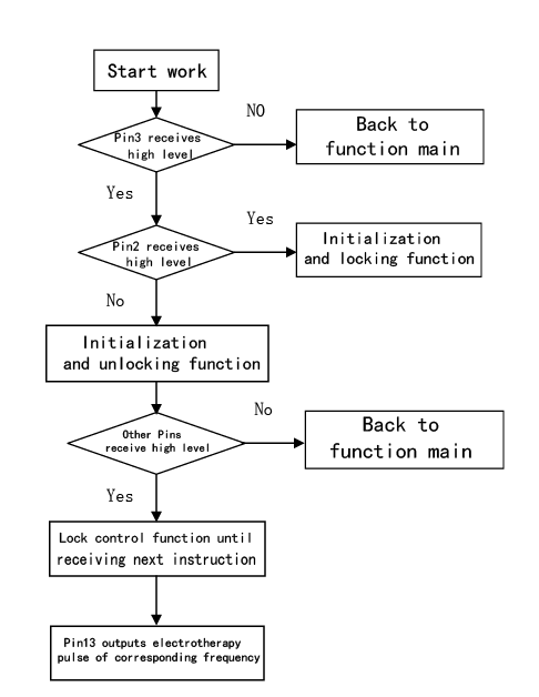
Figure 4. The flow chart of the software part.
Pin2 represents the power switch, while high and low levels of Pin3 represent the instrument's startup and shutdown states, respectively, in this application. The program's main function will only run if Pin3 has been toggled high once, however a high level on Pin2 will reset the program. The function main will keep running if there is no high level single from Pin2. Start up and initialization are done using the red button, whereas shutdown and initialization are done with the black button. Pin13 will keep sending pulses even if other color buttons are at a high level, because that indicates a certain indicator in the code. The value of the indicator and the pulse frequency generated by pin13 both change after the new button is pressed.
The treatment pulse frequency is realized, in part, by the delay function. To modify the pulse's duty cycle, the delay function is used to set the duration of the high and low levels. Modifying the lag time between the low and high levels affects the pulse's repetition rate.
Taking a one-gear loop function as an example:
{
digitalWrite(13, HIGH);
delayMicroseconds(100); //adjusting duty ratio
digitalWrite(13, LOW);
delayMicroseconds(1500 - 100); //adjusting frequency }
Through this function, we can adjust the pulse rate to just over 700 hertz (Hz). Accordingly, the waveform affected by the AC boost module is as follows (Affected by the AC boost module, the waveform changes from a square wave to a bidirectional pulse wave, and the duty cycle also changes. Incorporating these alterations into low-frequency electrotherapy may result in a more consistent analgesic effect.
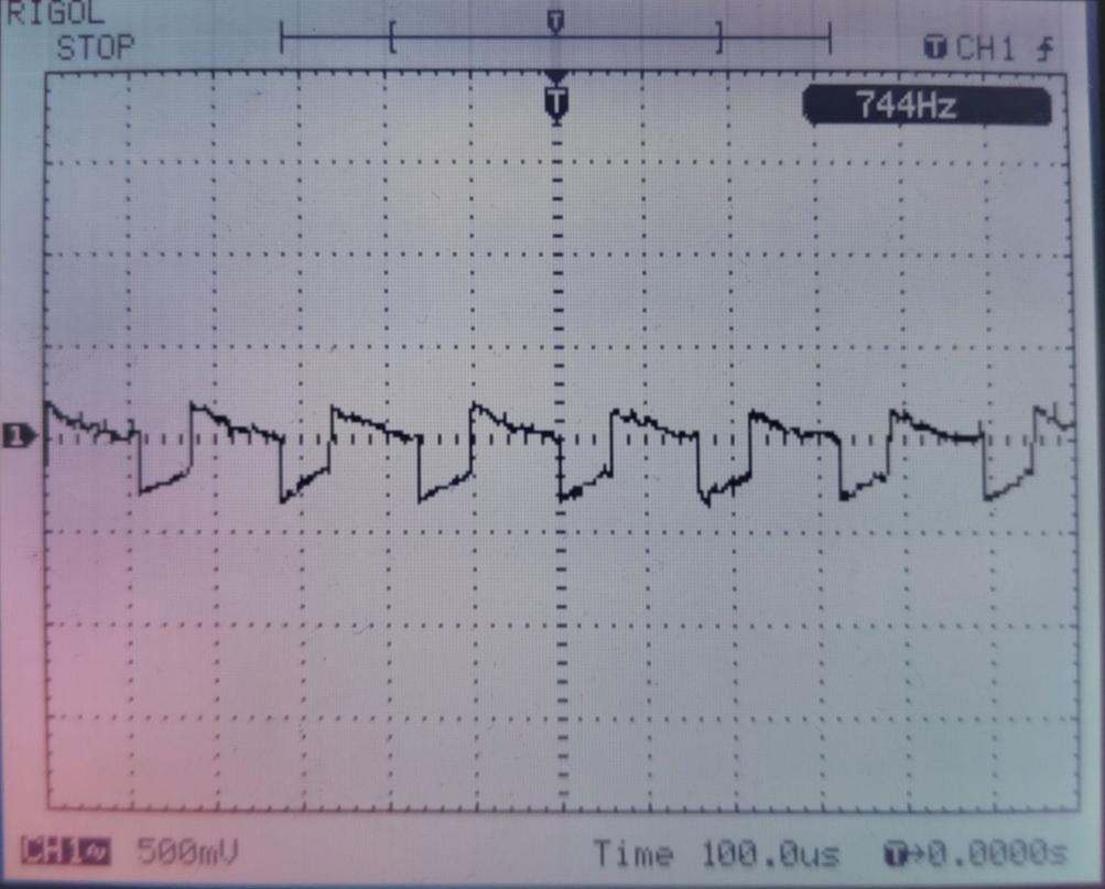
Figure 5. Oscillogram.
Figure 5 demonstrates that the output pulse voltage stays below the threshold of danger for human tissue, hovering about 20V.
Figure 6 depicts the final product. The instrument fits into a box that is 30cm 20cm when packaged.
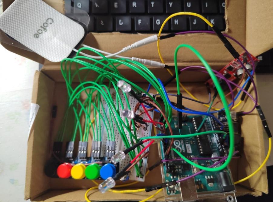
Figure 6. Picture of real products.
Once the test was completed, the electrode was attached to the skin, and as the gear was increased, individuals reported feeling increasingly intense stimulation and tremor. It has been demonstrated to have a therapeutic impact in reducing pain. Ten people were chosen to participate in the electrotherapy trial while their responses were studied. Ten participants reported experiencing clinically significant paralysis due to electrical stimulation. When asked about his muscle discomfort after intensive activity, one subject said it "clearly went" during the first ten seconds of the electrotherapy test, and the impact of paralysis to suppress pain lasted in a reasonably short time after the end of the short-term electrotherapy test. Data from controlled experiments demonstrate that the electrotherapy device is effective at reducing pain.
4. Conclusion
Electromagnetic fields (EMFs) have long been known to interact with living organisms and their cells and to bear the potential for therapeutic use [8].Different types of electric ions, making up a unique electrolyte, can be found in human bodily fluid. There are a number of physiological consequences caused by current flowing through a human body component that creates an electrical circuit. These include a heat effect, a stimulating effect, and a chemical effect. Electrotherapy can be broken down into high frequency, intermediate frequency, and low frequency categories based on the intensity with which different physiological effects are applied. To mask the sensation of pain, low-frequency electrical stimulation can be applied to the nerve cells involved. The purpose of this study is to test the effectiveness of low-frequency electrical therapy in alleviating pain through the stimulating effect on the human body. Some dangers can be associated with using electrotherapy. If the low-frequency current surpasses 5mA, electrotherapy is no longer a safe option. On the other hand, it is crucial to pay close attention to electrical protection during the experiment because any electronic device contains leakage current. To produce the desired electrotherapy pulses, the Arduino UNO equipment developed in this experiment is effective. The benefits of experimenting with the Arduino UNO board during development are crystal clear. The development board allows for easy and efficient adjustments and modifications during the early stages of design and sample production. In order to cut down on welding expenses and errors brought on by heat effects, developers can employ tools like breadboards and DuPont lines. Because of this, Arduino UNO is an excellent choice for developing electronic medical devices. While mostly flawless, this device does suffer from a few issues. Unfortunately, this electrotherapy tool cannot be used for very long because the Arduino UNO development board cannot handle the heat generated by its circuits. However, the final packaging of the electrotherapy device is complicated by the size of the Arduino UNO development board. However, the issue can be fixed by optimizing the code and reworking the hardware to use an Arduino nano instead of a larger development board.