

1. Introduction
3D scene modeling has witnessed significant advancements in recent years, driven by the growing need for realistic, immersive environments and accurate digital replicas of objects and structures. Laser scanning systems and image-based modeling and rendering technologies form the backbone of these developments, enabling the creation of detailed digital representations from physical data. As the demand for precise documentation and conservation of landscapes and heritage grows, optical remote sensing sensors have emerged as a crucial tool for capturing and preserving invaluable information across the globe [1]. The advent of Unmanned Aerial Vehicles (UAVs) has further revolutionized the field of 3D modeling. UAV platforms now offer a reliable and efficient source of data for inspection, surveillance, mapping, and 3D modeling applications, serving diverse industries such as agriculture, infrastructure, and disaster management. In addition, 3D models have become an indispensable part of various sectors, including manufacturing, research, and education. They are particularly valuable for assessing mechanical design elements and are increasingly used in architecture, medicine, and art for prototyping and visualization purposes [2].
Interaction with 3D models enhances the understanding of shape and spatial relationships between structures, allowing users to better grasp anatomical differences between individual bodies. This has particularly significant implications in the field of medicine, where medical professionals can now visualize and analyze complex structures with greater accuracy [3,4]. Image-based modeling has also proven to be an effective technique for creating 3D models of cultural heritage objects, thereby preserving and sharing valuable cultural information for future generations. The versatility of 3D modeling techniques has led to their widespread adoption across numerous industries and applications, including virtual reality experiences, video game environments, urban planning, and product design [5]. Learning 3D scene modeling equips individuals with valuable skills and tools that can be employed in various professional and academic fields. The ability to create accurate digital representations of real-world objects and environments holds immense potential for improved decision-making, enhanced collaboration, and a deeper understanding of complex spatial relationships [6]. As the demand for realistic, interactive digital experiences continues to grow, mastering 3D scene modeling is becoming increasingly crucial for professionals and researchers looking to stay ahead in their respective domains [7-10].
Although 3D modeling has been applied to various fields, there are insufficient literatures on 3D food production. Therefore, this paper takes Chinese cake as the model and builds the model with the help of Openscad.
2. Method
2.1. Rectangular Cabinet
The task of this work was to create a Chinese pastry. This chapter is about the modeling part, and this work made four models in total.
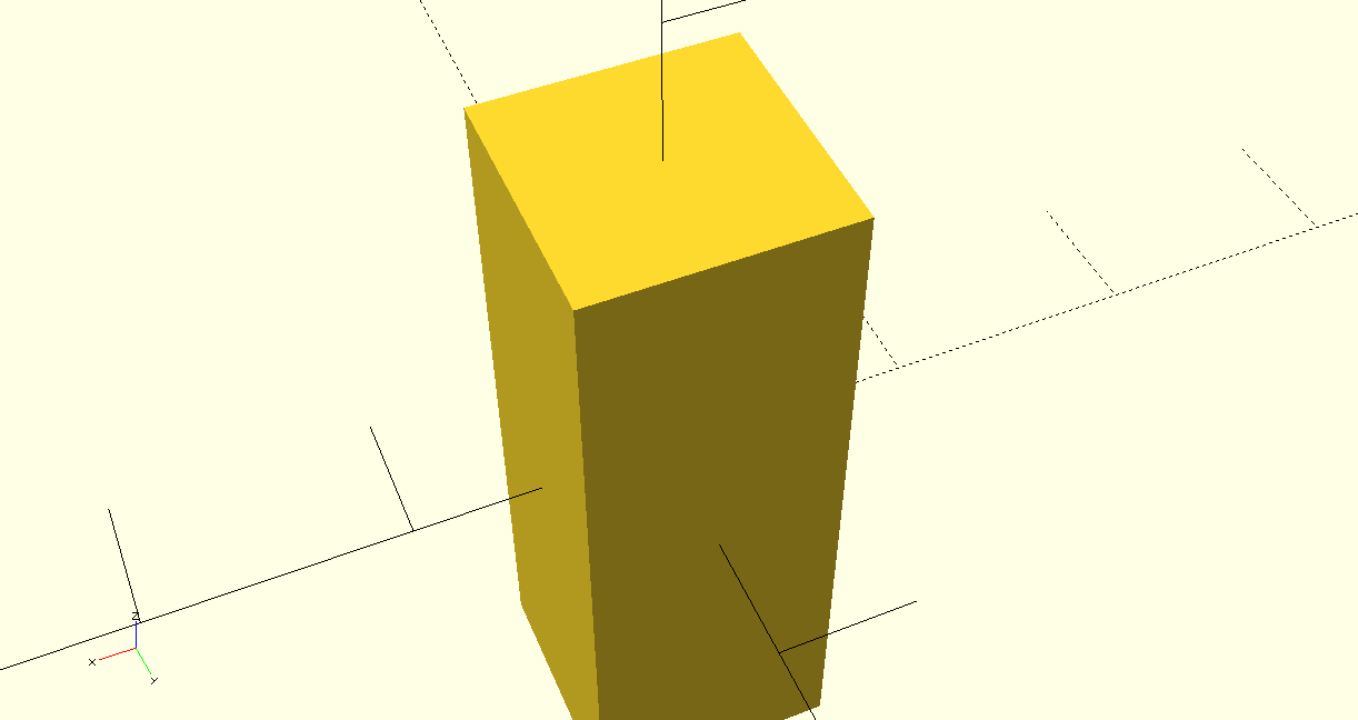
Figure 1: Rectangular Cabinet.
This is the first model, we use Openscad to complete the model, which this is a rectangular cabinet. It is very simple, using the code to set out the length, width and height of a cube. As shown in the figure 1, we first set a cube out with length, width and height of 10, 10 and 29 respectively and then set the whole rectangle in the middle position. A simple model of a rectangular cube is now complete.
2.2. Pallets
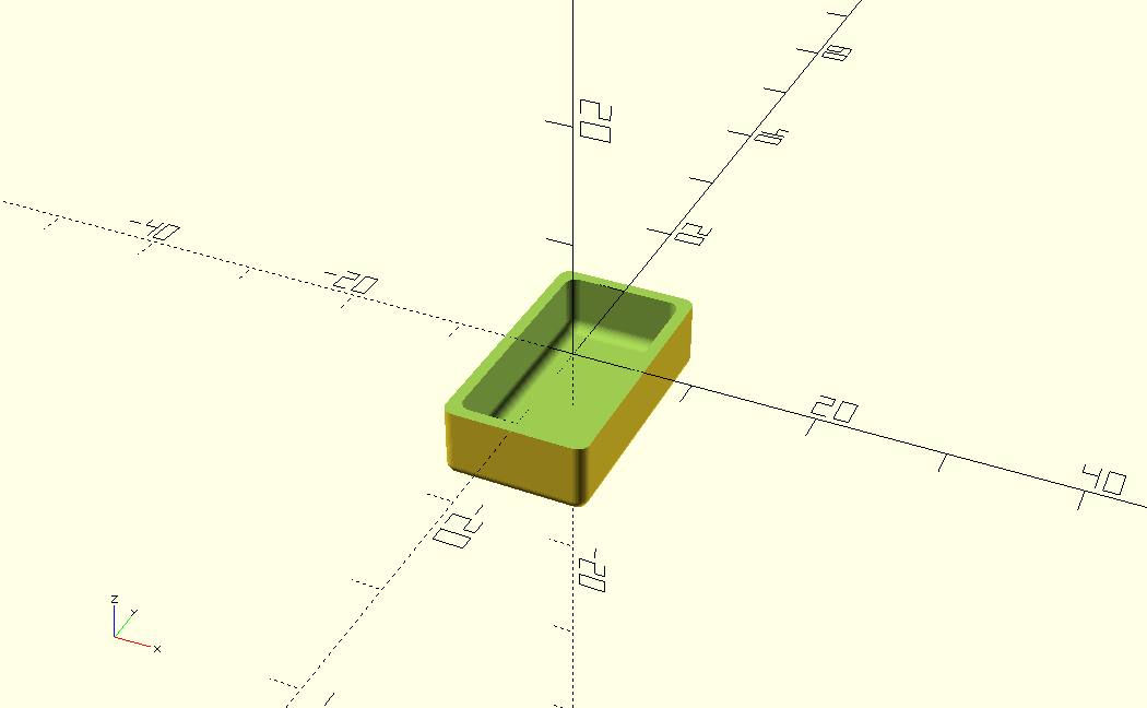
Figure 2: Pallets.
The second model is a plate for Pallets, which is a little different than the first model (Figure 2). In order to present the final effect, this work actually used three rectangles to take this paper intersection of each other and remove the excess parts to complete the plate.
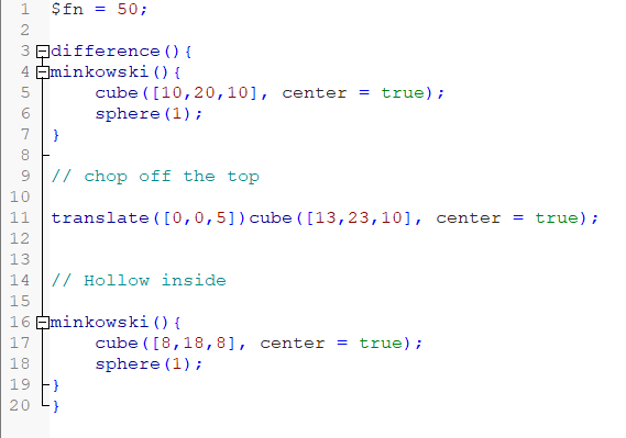
Figure 3: Code section.
As user can see above this work started by assigning a value of 50 to the variable $fn using $fn = 50z (Figure 3). This variable controls the number of segments used to render circular objects (such as spheres or cylinders) and can be used to control the resolution of these objects. this paper then use the difference () operation, which subtracts one or more of the shapes defined later from the first defined shape [8].
This is an interesting function minkowski () operation, which is used to calculate the Minkowski and geometric expansion operations for two or more 3D shapes. After that this paper created a rectangle using the following code cube ([10,20,10], center = true). This code creates a center-aligned rectangle with dimensions 10 x 20 x 10. This paper uses the sphere (1) code to round off the corners of the rectangle. The following code translate ([0,0,5]) cube ([13,23,10], center = true). This work creates a center-aligned rectangle with dimensions 13 x 23 x 10, and then move it 5 units in the positive direction along the Z axis. This rectangle will be used to excise a part of the shape from the previous one. Another minkowski () operation, again containing a center-aligned rectangle (size 8 x 18 x 8) and a sphere with a radius of 1. This creates a smaller rectangle with rounded corners.
In summary with the difference () operation, this work first computed the Minkowski sum of the two geometries (the rectangle with rounded corners and the sphere) and then subtracted a displaced rectangle from the resulting geometry. Finally, this work again computed the Minkowski sum for a smaller rectangular body with rounded corners and a sphere. The whole process results in a 3D model with rounded corners and a hollow section.
2.3. Sar-shaped Pastry
The third model is a star-shaped pastry, which does not directly use Opescad the software to draw a pentagram out. This would be more convenient but if the goal is to make a food, drawing a pentagram directly would make the whole object very thin and not look like a food (Figure 4). So this work decided to set up a rhombus with equal sides and then rotate the bottom point of the rhombus at an equal angle to make four copies of the same rhombus. Then this paper got a perfect chubby pentagram.
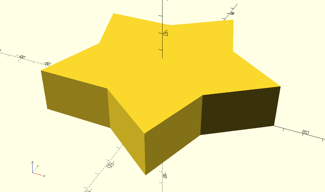
Figure 4: Sar-shaped pastry.
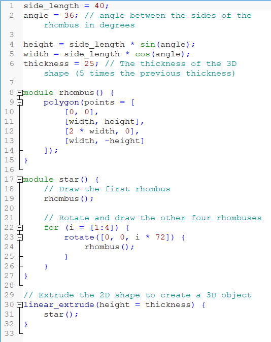
Figure 5: Code section.
As shown in the figure 5. this paper first set the parameters of the rhombus. side_length = 40; the side length of the rhombus is set to 40. angle = 36; the angle between the two sides of the rhombus is set to 36 degrees. height = side_length * sin (angle); the height of the rhombus is calculated. width = side_length * cos (angle); the width of the rhombus is calculated. angle); calculates the width of the rhombus. thickness = 25; sets the thickness of the 3D star object. Then this paper uses the module rhombus () {...}: command to define a module called rhombus for creating rhombuses. Inside the module, the polygon function is used to draw the rhombus based on the four vertex coordinates. module star () {...} directive is used to define a module named star, which is used to create star shapes. Inside the module, the first rhombus is drawn first, and then the other four are rotated around the center point and drawn through a for loop.Finally, linear_extrude(height = thickness) {...} command to stretch the 2D star along the Z-axis to create a 3D star object with the specified thickness.
2.4. Mooncake
The last model is also the most difficult one in our opinion. This paper first set up a square, then this paper set up four cylinders and then reduced the spacing of the cylinders and calculated the radius so that the diameters of the four cylinders add up to exactly one diameter longer than the length of the sides of the square. Then the four cylinders were rotated ninety degrees and copied to move the whole thing to the other side of the square, and then the two sets of cylinders were copied and moved to the opposite side of the square they were on to complete the mooncake (Figure 6).
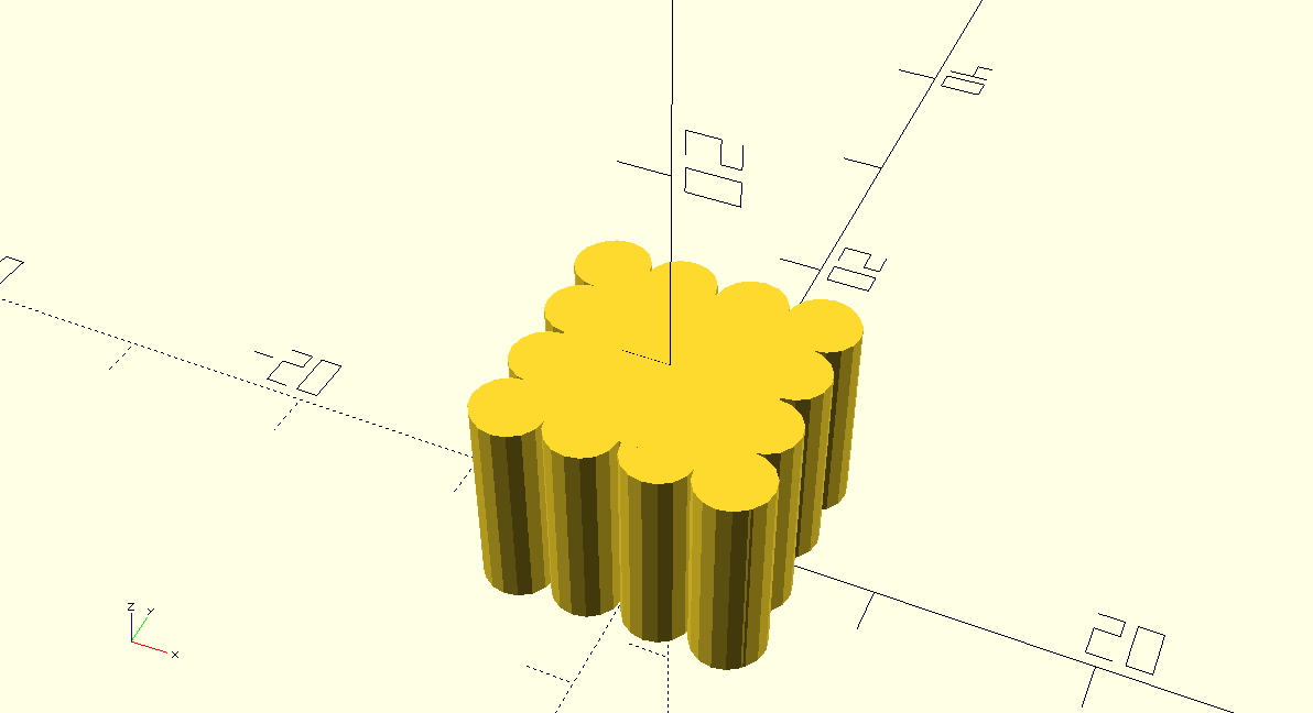
Figure 6: Mooncake.
As shown in the figure 7, this paper first set the parameters for the square and cylinder respectively. overlap = 0.1; // the overlap between the cylinders, used to allow some space between them num_cylinders = 4; // the number of cylinders, s = 10; // the length of the sides of the square, r = s/6; // the radius of the cylinder, h = s; / // the heights of the squares and cylinders.
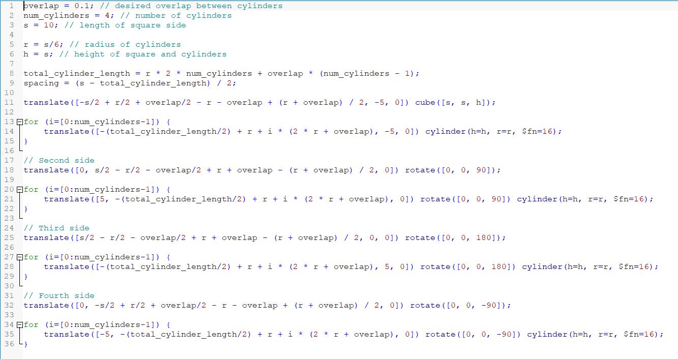
Figure 7: Code section.
After that this work calculate the total length total_cylinder_length occupied by all the cylinders and the spacing between them and the square sides. then the code generates the cylinders with four faces by looping through them. The coordinates of each cylinder are calculated based on its index in the loop, and are translated and rotated in the corresponding position and direction by the translate () and rotate () functions.
3. Result
In this study, we explored 3D modeling using OpenSCAD software during their research course. This work focused on creating four different models, including a wooden cabinet, a star-shaped pastry, a tray, and a mooncake (Figure 8). It provided valuable insight into the practical application of 3D modeling techniques, and innovative problem solving, and gave the researchers a code-based understanding of 3d modeling.
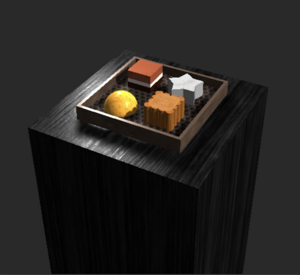
Figure 8: Final Result.
In this paper, 20 people were interviewed and evaluated on the following indicators (Table 1): geometry, style (color, pattern, etc.), fidelity, fashion, and refinement of details. In the evaluation of geometry, 15 people gave a score of 90 or more, two people gave a score of 80-90, and three people gave a score of 70-80.In the evaluation of style, 12 of the 20 participants gave a score of 90 or more, 6 gave a score of 80-90, and the remaining 4 gave a score of 70-80.Regarding fidelity, 10 of the 20 respondents provided scores of 90 or higher, 4 gave scores between 80 and 90, and 6 participants rated the category as 70-80.In the assessment of fashion ability, 13 of the 20 gave scores of 90 or higher, while 2 participants gave scores between 80 and 90 and the remaining 5 rated this aspect between 70 and 80.Finally, when assessing the refinement of details, 14 of the 20 respondents gave a score of 90 or more, while 3 gave a score between 80-90 and 3 participants provided a score between 70-80.
Table 1: Assessment result.
Score | Geometry | Style (Color,Pattern etc.) | Fidelity | Fashionability | Detail Refinement |
>90 | 15 | 12 | 10 | 13 | 14 |
80-90 | 2 | 6 | 4 | 2 | 3 |
70-80 | 3 | 2 | 6 | 5 | 3 |
4. Conclusion
This work demonstrated strong collaboration skills and used OpenSCAD software to solve complex problems. By creating detailed and accurate models, the work demonstrated the potential of 3D modeling in a variety of applications and gained a deeper understanding of the process of 3d modeling, or cg animationz production, at the code level. Overall, this study has achieved significant results in the field of 3D modeling. The researcher demonstrated the mastery of OpenSCAD software and showcased the ability to create four distinct models. Through a collaborative and innovative problem-solving approach, skills in a practical setting are demonstrated, which has certain reference value.